1-4
Catalyst 3750-X and 3560-X Switch Software Configuration Guide
OL-25303-03
Chapter 1 Configuring STP
Understanding Spanning-Tree Features
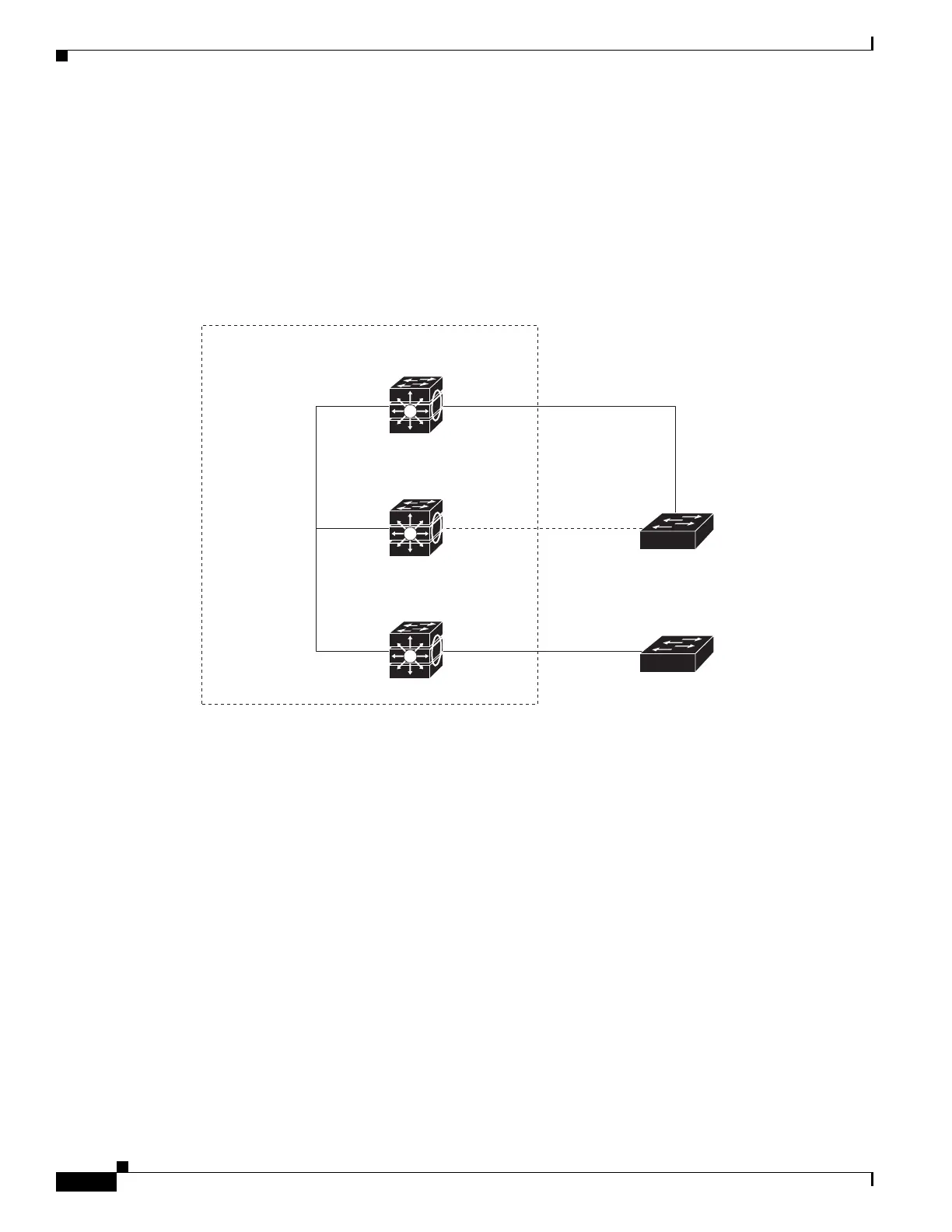
Only one outgoing port on the stack root switch is selected as the root port. The remaining switches
in the stack become its designated switches (Switch 2 and Switch 3) as shown in Figure 1-1 on
page 1-4.
• The shortest distance to the root switch is calculated for each switch based on the path cost.
• A designated switch for each LAN segment is selected. The designated switch incurs the lowest path
cost when forwarding packets from that LAN to the root switch. The port through which the
designated switch is attached to the LAN is called the designated port.
Figure 1-1 Spanning-Tree Port States in a Switch Stack
All paths that are not needed to reach the root switch from anywhere in the switched network are placed
in the spanning-tree blocking mode.
Switch 1
Switch stack
DP Outgoing RP
Switch 2
RPStackWise Plus
port connections
BP
DP
Switch 3
Switch A
Switch B
RP
DP
Spanning-tree root
RPDP
RP = root port
DP = designated port
BP = blocked port
159890