I nse rt wor kpi e ce
After inserting the workpiece into the rotation axis, the workpiece zero point must be placed on the
material surface vertically above the center. For an A-axis of rotation parallel to the X-axis, move to
the workpiece so that the tip of the cutter just touches the top of the cylinder (pipe, rod, etc.) and set
the Y and Z coordinates to zero.
P robi ng t h e w o rkp i ec e
In order to find exactly the center point in
the Y-direction, you can either touch the
workpiece on both sides laterally, or
instead of the actual workpiece first clamp
a cylindrical pin in the jaw chuck whose
diameter matches that of the tool, pin and
cutter congruent drive over each other, and
first set the Y axis to zero. Then clamp the
real workpiece again and set the Z
coordinate to zero on the top.
Load N C progra m
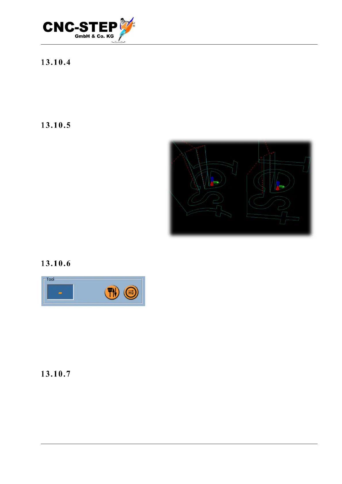
Open now the NC Program. The tool path is initially
displayed "flat", i.e. parallel to the XY plane.
Now go to the tool path dialog via the button to the right of
the tool display (see picture above right). Switch to the
"Drum Engraving" tab and activate the check mark "Engrave drum active". If you now enter the
correct workpiece diameter (or optionally radius or circumference) and exit the dialog with "OK",
the graphic is rebuilt and the tool path appears curved, wrapped around an imaginary cylinder. The
picture on the left shows an engraving once with drum engraving turned on and once "flat", with
drum engraving turned off.
Tur n off dr um eng rav i ng
If you want to process a "normal" workpiece after finishing work, you should switch off the drum
engraving option again. If the train preview looks strange, or you get inexplicable error messages,
this may be a sign that you have forgotten it.


 To Next Page