Calibration - PWM output
In the case of milling machines with a
high-frequency spindle, the spindle
speed is set using the PWM output or the
laser power during laser engraving. The
mapping of the S value in the NC
program can be adjusted via the
calibration function, it is set which
minimum and maximum S value
corresponds to which voltage value.
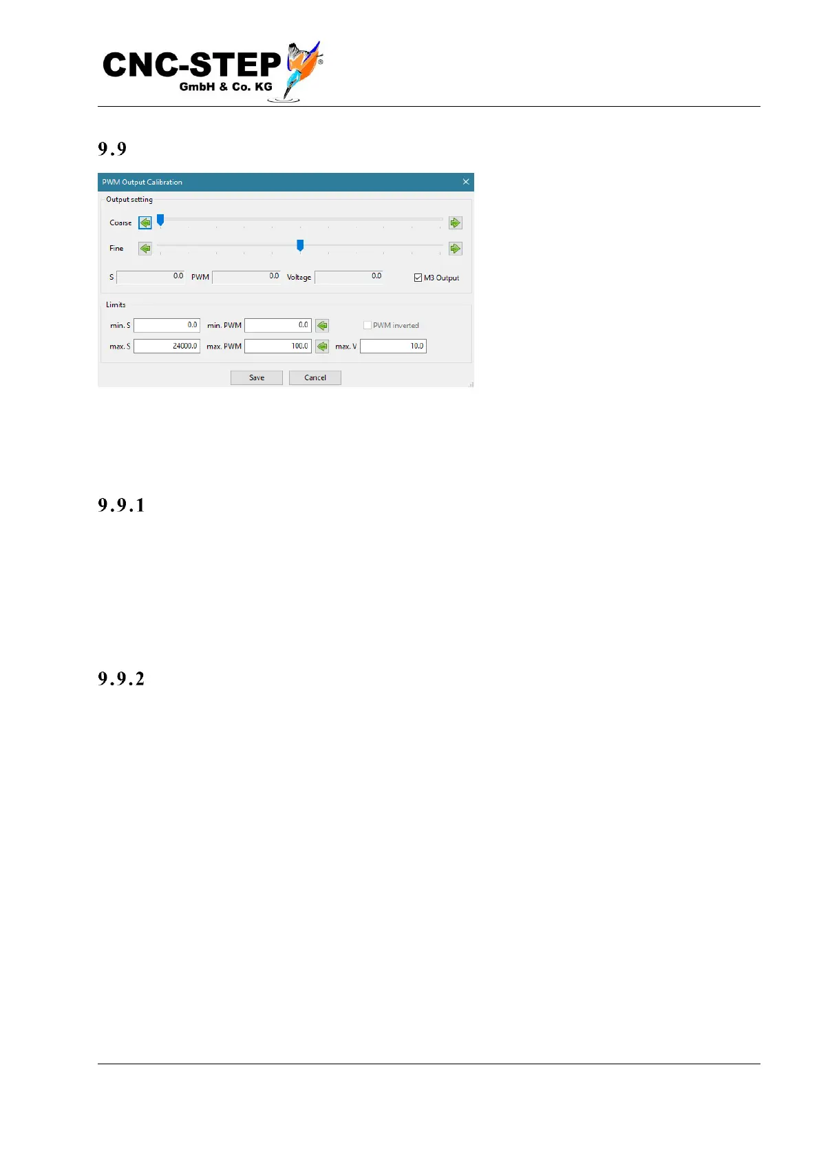
To do this, first enter the permissible range for the S value (speed or power level) at the bottom left.
The middle column shows the assigned values for the minimum and maximum duty cycle of the
PWM output in percent. The value for the maximum voltage at the bottom right is just for control.
Te sti ng
In the upper part of the window, the setting can be tested. When the M3 output is turned on, the
spindle should rotate at the indicated speed, or the displayed voltage at the analog output should be
measured. If this deviates, it can be adjusted by adjusting the values for min and max PWM. The
arrow button to the right of the PWM values adopts the currently set value from the upper area in
the input field to the left.
La se r Applic a t ions
When laser engraving, the output cannot be tested directly because a hole would burn into the
material when the laser is stationary. Here, the PWM setting must be determined with a special test
program. This is described in the laser unit manual.