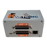
Prese n tat io n i n t h e gr aph i c
As you can see from the picture, the
working surface protrudes to the right
out of the processing area of the
machine, and should be moved to the
left, in the direction of smaller X-
values.
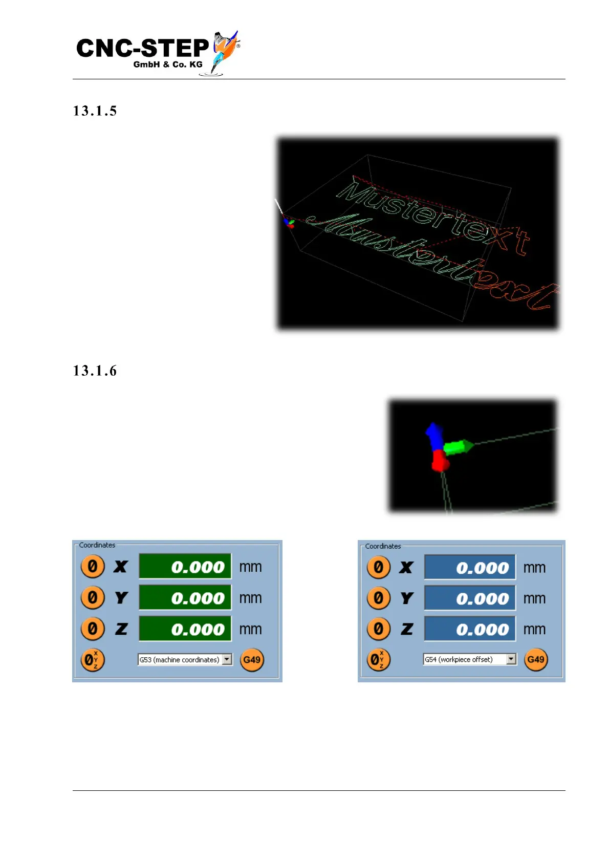
Set z ero point
The following description assumes that the zero point in the
drawing is at the top of the material, as in the example of the
image, and at the bottom left in the X / Y direction. If the
coordinate display on the top right screen still has a green
background color, then no workpiece offset has been
selected and "G53 (Machine Coordinates)" is displayed
below the coordinates.
First select an offset there, e.g. "G54 (workpiece offset)". The coordinate display changes to blue
background color.