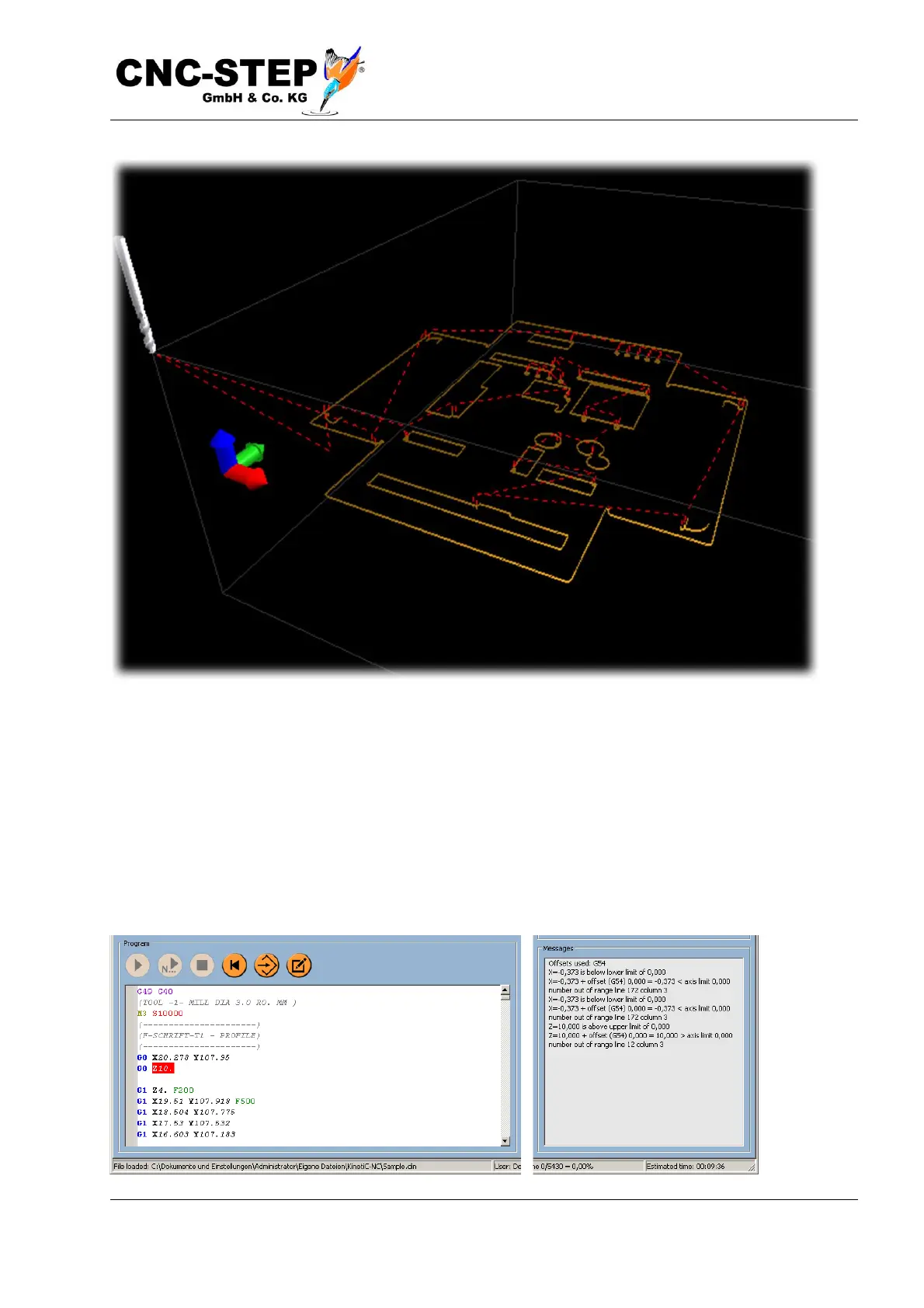
The picture above shows an example of a sheet metal part with several holes and recesses. Milling
paths along the contour are normally displayed in green (possibly with different tools in other
colors), rapid traverse movements with dashed red lines. The position of the zero point is
represented by the three arrows in red, green and blue.
The text window below shows the source code of the program. Normally, the first few lines contain
comments with the name of the part and possibly further information about date of creation, tools
used and more.