FC 300 Design Guide
How to Program
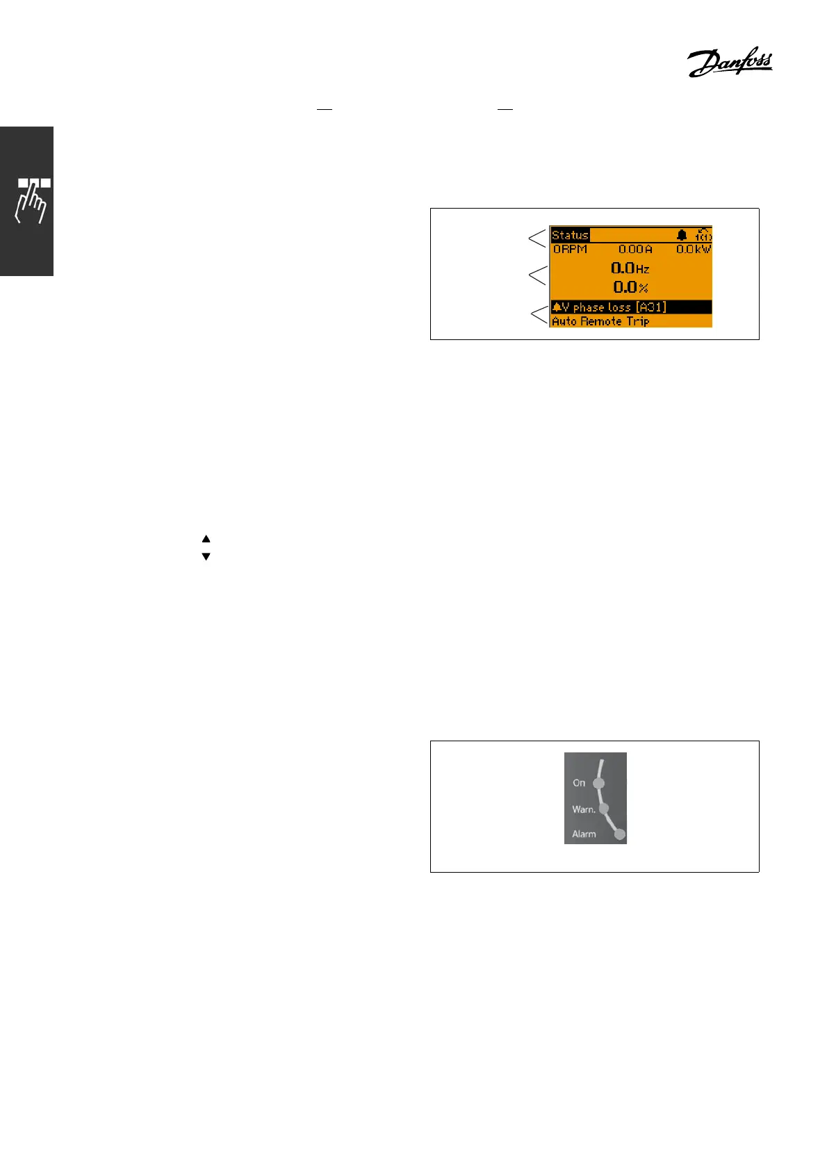
The LCD display has back lighting and a total of 6 alpha-numeric lines. The display lines show the direction of
rotation (arrow), the chosen Set-up as w ell as the programming Set-up. The display is divided into 3 sections:
Top section shows up to 2 measurements
in normal operating status.
ThetoplineintheMiddle section shows up to
5 measurements with related units, regardless o f
status (except in the case of alarm/warning).
Bottom section always shows the state of the
adjustable frequency drive in Status mode.
130BP074.10
Top section
Middle section
Bottom section
The Active Set-up (selected as the A ctive Set-up in par. 0-10) is shown. When programming another Set-up
other than the Active Set-up, the number of theprogrammedSet-upappearstotheright.
Display Contrast Adjustment
Press [status] and [
] for darker disp lay
Press [status] and [
]forbrighterdisplay
Most FC 300 parameter set-ups can be changed immedia tely via the control panel, unless a password
has been created via p ar. 0-60 Main Menu Password or via par. 0-65 Quick Menu Password.
LEDs:
If certain threshold values ar e exceeded, the alarm and/or warning LED light(s) up. A
status a nd alarm text appear on the control panel.
The on LED is ac tivated when the adjustable frequency drive receives line voltage or vi a a DC bus
terminal or 24 V external supply. At the same time, the back light is on.
• Green LED/On: Control section is working.
• Yellow LED/Warn.: Indicates a warning.
• Flashing Red L ED/Alarm: Indicates an alarm.
130BP040.10
136
MG.33.B6.22 - VLT is a registered Danfoss trademark

 Loading...


