FC 300 Design Guide
How to Program
Select Linked to Hand / Auto [0] to use the local
reference when in Hand mode; or the remote
reference when in Auto m ode.
Select Remote [1]tousetheremotereference
in both Hand mode and Auto mode.
Select Local [2] to use the local reference in
both Hand mo de and Auto mode .
3-14 Preset Relative Reference
Range:
-100.00 - 100.00%
*
0.00%
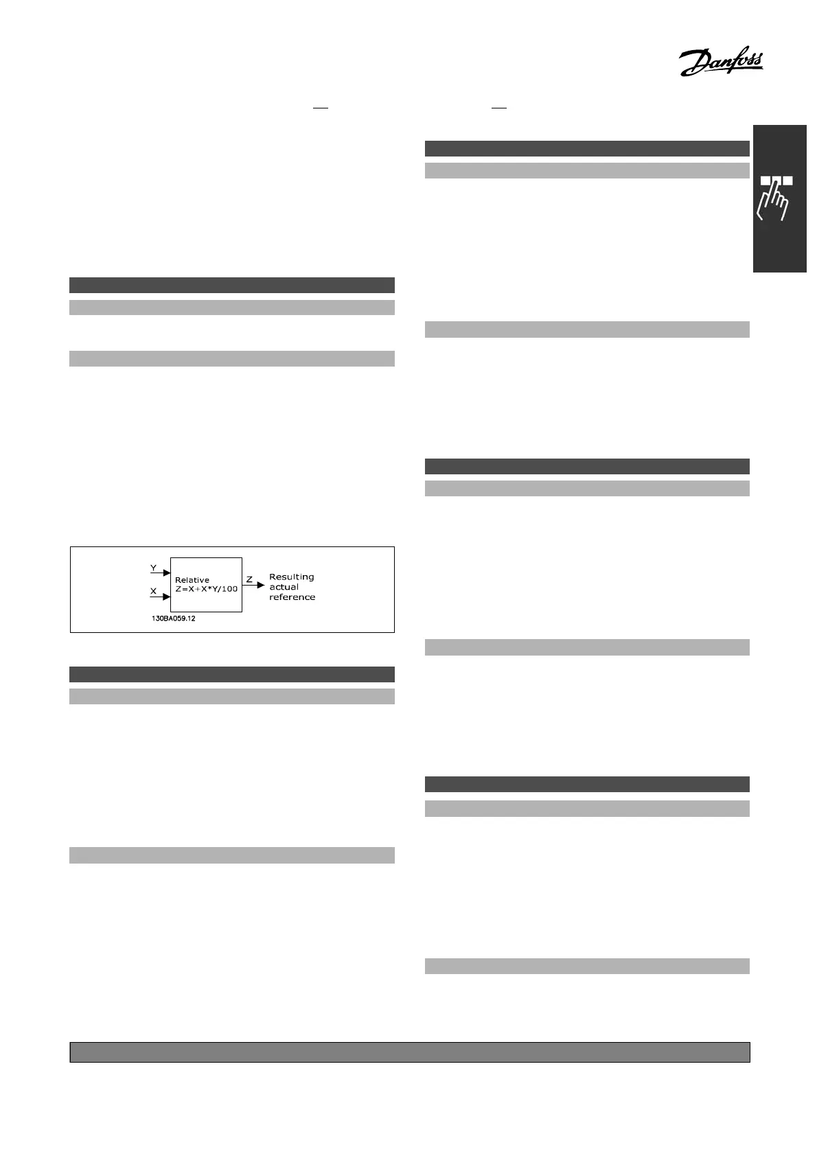
Function:
Define a fixed value (in % ) to be added to the
variable value (defined in par. 3-18 Relative Scaling
Reference S ource). The sum of the fixed and
variable values (labeled Y in the illustration below)
is multiplied with the ac tual reference (labele d
X in the illustration below). This product is then
added to the actual reference ( X+X*Y/1 00 ) to
give the resulting actual refere nce.
3-15 Refere nce Resource 1
Option:
No function [0]
*
Analog input 53 [1]
Analog input 54 [2]
Frequency input 29 [7]
Frequency input 33 [8]
Local bus reference [11]
Digital pot.meter [20]
Function:
Selectthereferenceinputtobeusedforthefirst
reference signal. Par. 3-15, 3-16 an
d3-17define
up to three different reference signals. The sum of
these reference signals defines the actual reference.
This parameter cannot be adjusted w
hile
the motor is running.
3-16 Reference R esource 2
Option:
No function [0]
Analog input 53 [1]
Analog input 54 [2]
Frequency input 29 [7]
Frequency input 33 [8]
Local bus reference [11]
*
Digital pot.meter [20]
Function:
Select the reference input to be used for the second
reference signal. Par. 3-15, 3-16 and 3-17 define
up to three different reference signals. The sum of
these reference signals defines the actual reference.
This parameter cannot be adjusted while
the motor is running.
3-17 Reference R esource 3
Option:
No function [0]
Analog input 53 [1]
Analog input 54 [2]
Frequency input 29 [7]
Frequency input 33 [8]
*
Local bus reference [11]
Digital pot.meter [20]
Function:
Select the referen ce input to be used for the third
reference signal. Par. 3-15, 3-16 and 3-17 define
up to three different reference signals. The sum of
these reference signals defines the actual reference.
This parameter cannot be adjusted while
the motor is running.
3-18 Relativ e Sc alin g Reference Resource
Option:
*
No function [0]
Analog input 53 [1]
Analog input 54 [2]
Frequency input 29 [7]
Frequency input 33 [8]
Local bus reference [11]
Digital pot.meter [20]
Function:
Select a variable value to be added to the fixed value
(defined in par. 3-14Preset Relative Reference). The
sum of the fixed and variable values (labelled Y in
*
default setting ()display text []value for use in communication via serial communication port
179
MG.33.B
6.22 - V LT is a registered Danfoss trademark

 Loading...


