FC 300 Design Guide
How to Program
the illustration below) is multiplied wit h the actual
reference (labelled X in the illustration below).
This product is then added to the actual reference
(X+X*Y/100) to give the resulta nt actual reference.
This parameter cannot be adjusted while
the motor is running.
3-19 Jog Speed [RPM]
Range:
0-par. 4-13RPM
*
150 RPM
Function:
Enter a value for the jog speed n
JOG
,whichisa
fixed output speed. The adjustable frequency
drive runs at this speed w hen the jog function
is activated. The maxim um limit is defined in
par. 4-13 Motor Speed High Limit (Hz).
See also par. 3-80.
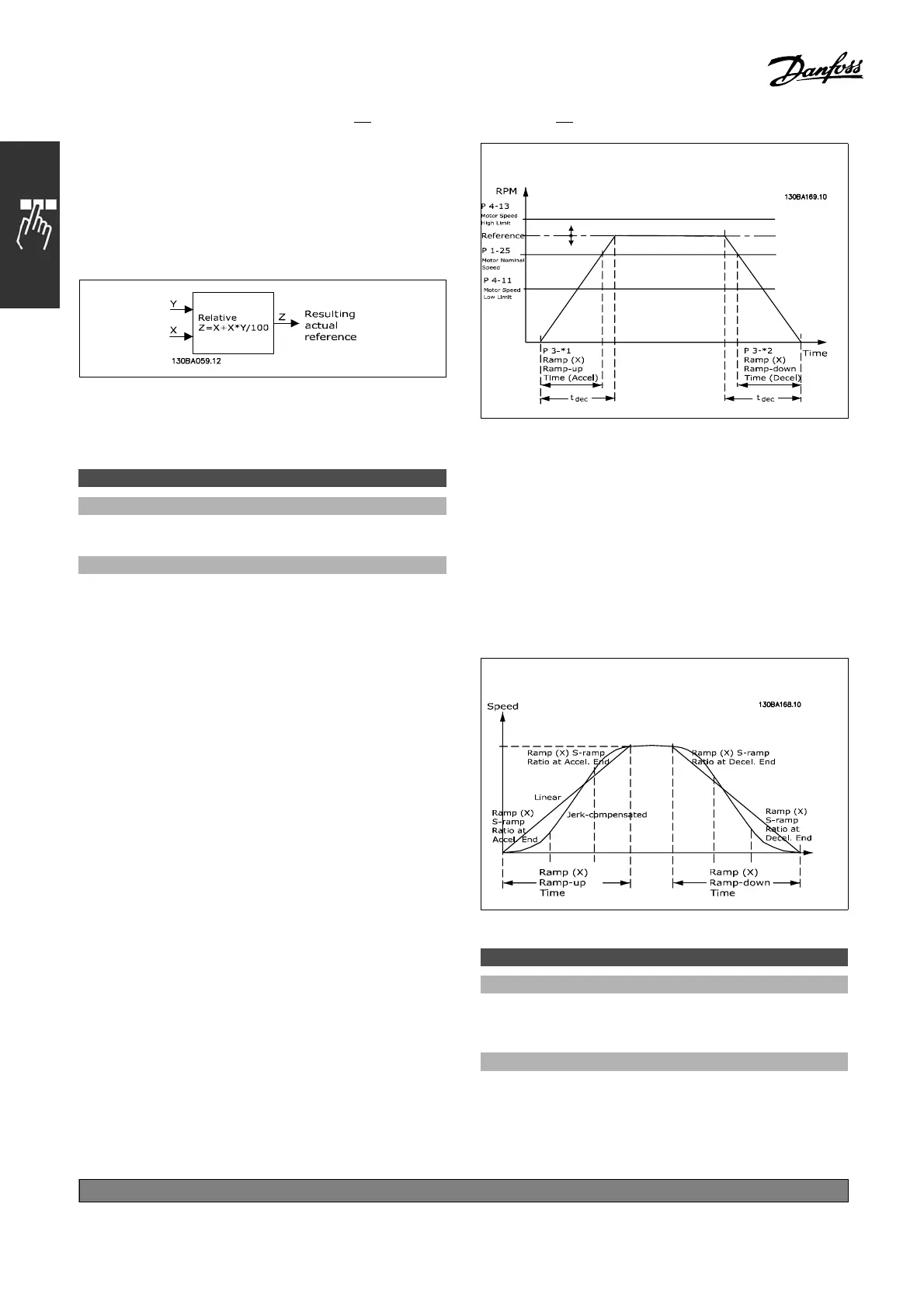
" Ramps
3-4* Ramp 1
For each of four ramps (par. 3-4*, 3-5*, 3-6*
and 3-7*), configure the ramp parameters:
ramp type, ramping times (duration o f
acceleration and deceleration) and level of
jerk compensation for S ramps.
Start by se tting the linear ramping t imes
corresponding to the figures and formulas.
If S -ramps are selected, then set t he level of
non-linear jerk compensation required. Set
jerk compensation by defining the proportion of
ramp-up and ramp-down times where acceleration
and deceleration are variable (i.e., increasing
or decreasing). T he S-ramp acceleration and
deceleration settings are defined as a pe rcentage
of the actual ramp time.
3-40 Ramp 1 Type
Option:
*
Linear [0]
S-ramp [1]
Function:
Selects the desired ramp type, depending on
requirements for
acceleration/deceleration.
A linear ramp will give constant acceleration
during ramping. An S-ramp will give
*
default setting ()display text []value for use in communication via serial communication port
180
MG.33.B
6.22 - V LT is a registered Danfoss trademark

 Loading...


