FC 300 Design Guide
How to Program
• Freeze ref [19]: Free ze the actual reference.
The frozen reference is now the point of
enable/condition for Speed up and Speed
down to be used. If Speed up/down is used,
the speed change always follows ramp 2
(par. 3-51 and 3-52) in the range 0 - par.
3-03 Maximum Reference.
• Freeze output [20]: Freeze the actual motor
frequency (Hz). The frozen motor frequency
is now the point of enable/condition for Speed
up a n d Speed down to be used. If Speed
up/down is used, the speed chang e always
follows ramp 2 (par. 3-51 and 3-52) in the
range 0 - par. 1-23 Motor Frequency.
NOTE
When Freeze output is active, the
frequency converter cannot be stopped
via a low ‘start [13]’ signal. Stop the
frequency converter via a terminal programmed for
Coasting inverse [2] or Coast and reset, inverse.
• Speedup[21]: Select Speed up and Speed
down if digital control of the up/down speed is
desired (motor potentiometer). Activate this
function by selecting either Freeze reference or
Freeze output. When Speed up is acti vated for
less than 400 msec. the res ulting reference will
be increased by 0.1 %. If Speed up is activated
for more than 400 msec. the resulting refer
ence
will ramp according to Ramp 2 in par. 3-41.
Shut down Catch up
Unchanged speed 0 0
Reduced by %-value 1 0
Increased by % - value 0 1
Reduced by %-value 1 1
• Speed down [22]:SameasSpeedup[21].
• Set-up select bit 0 [23] : Select Set
-up
select bit 0 or Select Set- up select bit 1 to
select one of the four set-ups. Set par. 0-10
Active Set-up to Multi Set-up.
• Set-up select bit 1 [24] (Default Digital input
32): Same as Set-up select bit 0 [23].
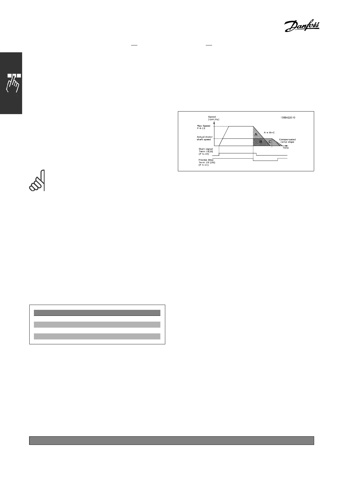
• Precise stop inv. [26]:Prolon
gthestopsignal
to give a precise stop independent of speed.
Precise stop inverse function is available
for terminals 18 or 19.
• Precise start, stop [27]:Usewhen
Precise ramp stop [0] is selected in par
1-83 P recise stop function.
• Catch up [28]:SelectCatchup/Slow
down to increase or reduce the reference
value set in par. 3-12.
• Slow down [29]:SameasCatchup[28].
• Counter input [30]: Select Counter input if
you want to use the Precise stop function in par.
1-83 as Counter stop or speed compensated
counter stop with or without reset. T he counter
value must be set in par. 1-84.
• Pulse input [32]: SelectPulseinputwhen
using a pulse sequence as either reference or
feedback. Scali ng is done in par. group 5-5*.
• Ramp bit 0 [34]
• Ramp bit 1 [35]
• Mains failure inverse [36]:Selecttoactivate
par. 14-1 0 Mains Failure. Mains failure inverse
is active in the Logic .0. situation.
• Latched Precise Stop inverse [41]:Send
a latched stop signal when the prec ise stop
function is activated in pa r. 1-83 Precise
Stop Function. See selection [26]. The
Latched P recise stop inverse function is
available for terminals 18 or 19.
• DigiPot Increase [55]:Usetheinpu
tasan
INCREASE signal to the Digital Potentiometer
function described in parameter group 3-9*
• DigiPot Decrease [56]:Usetheinp
ut as a
DECREASE signal to the Digital Potentiometer
function described in parameter group 3-9*
• DigiPot Clear [57]:Usetheinp
ut to CLEAR
the Digital Potentiometer reference described
in parameter group 3-9*
*
default setting ()display text []value for use in communication via serial communication port
194
MG.33.B
6.22 - V LT is a registered Danfoss trademark

 Loading...


