FC 300 Design Guide
Troubleshooting
WARNING 5
DC v o ltage high:
The interme diate circuit voltage (DC) is higher than
the overvoltage limit o f the control system . The
adjustable frequency drive is still active.
WARNING 6
DC link vol tage low
Theintermediatecircuitvoltage(DC)isbelow
the undervoltage limit of the control system. The
adjustable frequency drive is still active.
WARNING/ALARM 7
DC overvoltage:
If the intermediate circuit voltage exceeds the limit,
the adjustable frequency drive trips after a time.
Possible corrections:
Select O
ver Voltage Control function in par. 2-17
Connect a brake resistor
Extend the ramp time
Activate functions in par. 2-10
Increase par. 14-26
Selecting OVC function w ill extend the ramp times.
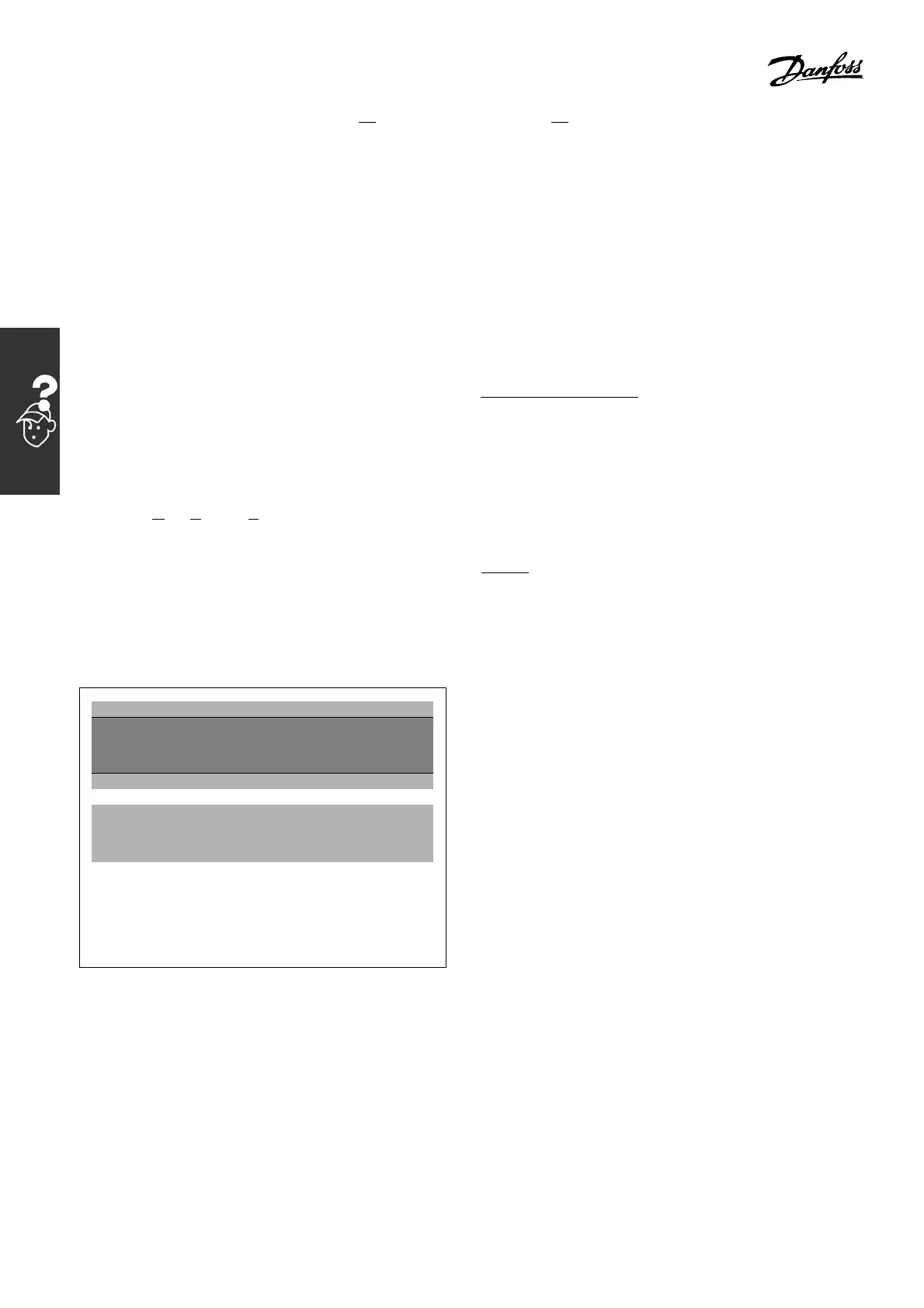
Alarm/warning limits:
FC 102 Series 3 x 200-240
VAC
3 x 380-500
VAC
[VDC] [VDC]
Undervoltage 185 373
Voltage warning low 205 410
Voltage warning
high (w/o brake -
w/brake)
390/405 810/840
Overvoltage 410 855
The voltages stated are the intermediate circuit
voltage of the FC 100 with a tolerance of ± 5%.
The corresponding line voltage is the intermediate
circuit voltage (DC link) divided by 1 .35.
WARNING/ALARM 8
DC undervoltage:
If the intermed iate circu it voltage (DC) drops
below the “voltage warning low” limit (see table
above), the adjustable frequency drive checks
if 24 V backup supply is connected.
If no 24 V backup supply is connected, the
adjustable frequency drive trips after a given
time depending on the unit.
To check whether the supply voltage matches
the adjustable frequency drive, see the
G
eneral Specifica tions.
WARNING/ALARM 9
Inverter overloaded:
The adjustable frequency drive is about to cut
out because of an overload (too high current for
too long). The counter for electronic, thermal
inverter protection gives a warning at 98%
and trips at 100%, while giving an alarm. You
c
annot reset the adjustable frequency drive
until the counter is below 90%.
The fault is that the adjustable frequency
drive is overloaded by more than nominal
current for too long.
WARNING/ALARM 10
Motor ETR over:
According to the electronic thermal protection (ETR),
the motor is too hot. You can choose whether the
adjustable frequency drive should give a warning or
an alarm when the counter reaches 100% in par.
1-90. The fault is that the motor is overloaded by
more than nominal current for too long. Make sure
that the motor par. 1-24 is set correctly.
WARNING/ALARM 11
Motor thermistor overtemp:
The thermistor or the thermistor connection
is disconnected. You can choose whether the
adjustable frequency drive should give a warning or
an alarm in par. 1-90. M ake sure the thermistor
is connected correctly between termina
l53or
54 (analog voltage input) and ter mi nal 50 (+
10 V sup ply), or between terminal 18 or 19
(digital input PNP only) and te rmina
l50. Ifa
KTY sensor is used, check for correct connection
between terminal 54 and 55.
300
MG.33.B6.22 - VLT is a registered Danfoss trademark

 Loading...


