FC 300 Design Guide
FC 300 Selection
Analog inputs:
Number of analog inputs ................................................................................................................ 2
Terminal number ................................................................................................................... 53, 54
Modes ................................................................................................................. Voltage or current
Mode select .......................................................................................... Switch S201 and switch S202
Voltage m ode .............................................................................. Switch S201/switch S202 = OFF (U)
Voltage level .......................................................... FC 301: 0 to + 10 / FC 302: -10 to +10 V (scalable)
Input resistance, R
i
.................................................................................................... approx. 10 kΩ
Max. voltage ........................................................................................................................ ± 20 V
Current mode ................................................................................ Switch S201/switch S202 = ON (I)
Current level ................................................................................................. 0/4 to 20 m A ( scalable)
Input resistance, R
i
.................................................................................................... approx. 200 Ω
Max. current ........................................................................................................................ 30 mA
Resolution for analog inputs ......................................................................................... 10 bit (+ sign)
Accuracy of analog inputs ......................................................................... Max. error 0.5% of full scale
Bandwidth ........................................................................................ FC 301: 20 Hz / FC 302: 100 Hz
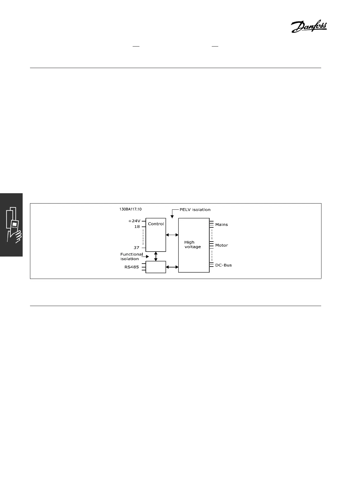
The analog inputs are ga lvanically isolated from the supply voltage (PEL V) and other high-voltage terminals.
Pulse/encoder inputs:
Programmable pulse/encoder inputs ............................................................................................. 2/1
Te rminal number pulse/encoder ........................................................................ 29, 33
1)
/ 18, 32, 33
2)
Max. frequency at terminal 18, 29, 32, 33 .................................................... 110 kHz (push-pull driven)
Max. frequency at terminal 18, 29, 32, 33 ........................................................... 5 kHz (open collector)
Min. frequency at terminal 18, 29, 3 2, 33 .................................................................................... 4 Hz
Voltage level ............................................................................................. see section on Digital input
Maximum voltage on input ................................................................................................... 28 V DC
Input resistance, R
i
...................................................................................................... approx. 4 kΩ
Pulse input accuracy (0.1 - 1 kHz) .......................................................... Max. error: 0.1% of full scale
Encoder input accuracy (1 - 110 kHz) ..................................................... Max. error: 0.05% of full scale
The pulse and encod er inputs (terminals 18, 29, 32, 33) are galv anically isolated from the
supply voltage (PELV) and other high-voltage terminals.
1) Pulse inputs are 29 and 33
2) Encoder inputs: 32 = A, and 33 = B
62
MG.33.B6.22 - VLT is a registered Danfoss trademark

 Loading...


