Barcode Scanning Features
212
DS8110 Barcode Scanner
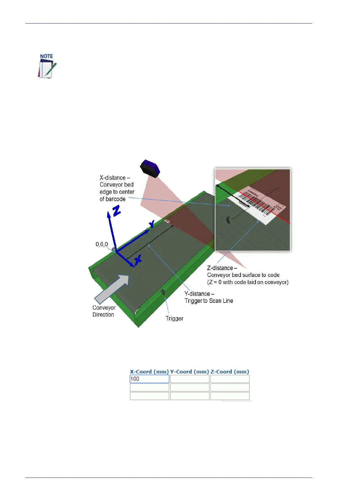
Top-Mounted Barcode Scanner Calibration Using PackTrack
With the belt stopped, measure and enter the barcode XYZ coordinate data for
each scanner as follows:
1. Make sure that the intended scanner (in a multi-head system) has been
sel
e
cted from the drop-down lists at the top of the wizard window.
2. Start by laying a system barcode on the conveyor bed in the laser line as
c
l
ose to the left edge (X=0 edge) as possible. See illustration below.
3. Measure the distance for X from the edge of the conveyor bed to the center
of the barcode, and enter that distance in the first box under X-Coord (mm)
in the PackTrack Calibration Wizard. Your measurements will likely differ
from those shown below.
4. Measure the distance for Y from the trigger (PS line) to the barcode scan-
ner's laser line on the barcode, and enter that distance in the first box
under
Y-Coord (mm). Your measurements will likely differ from those
shown below.
It is not possible to illustrate every possible installation angle and scanner mounting
position in this manual. Use the following steps as a general guide to calibrating each
system scanner using barcodes in three positions. You will need to make adjustments
to the label/box position based on your situation. It is, however, important to note the
fixed XYZ coordinates of the conveyor.
 Loading...