Chapter 7 Optional AccessoriesMH300
B. Casing without mechanical fixed part
This solution has higher performance: high initial magnetic permeability, high saturation induction
density, low iron loss and perfect temperature characteristic. If the zero-phase reactor does not need to be
fixed mechanically, use this solution.
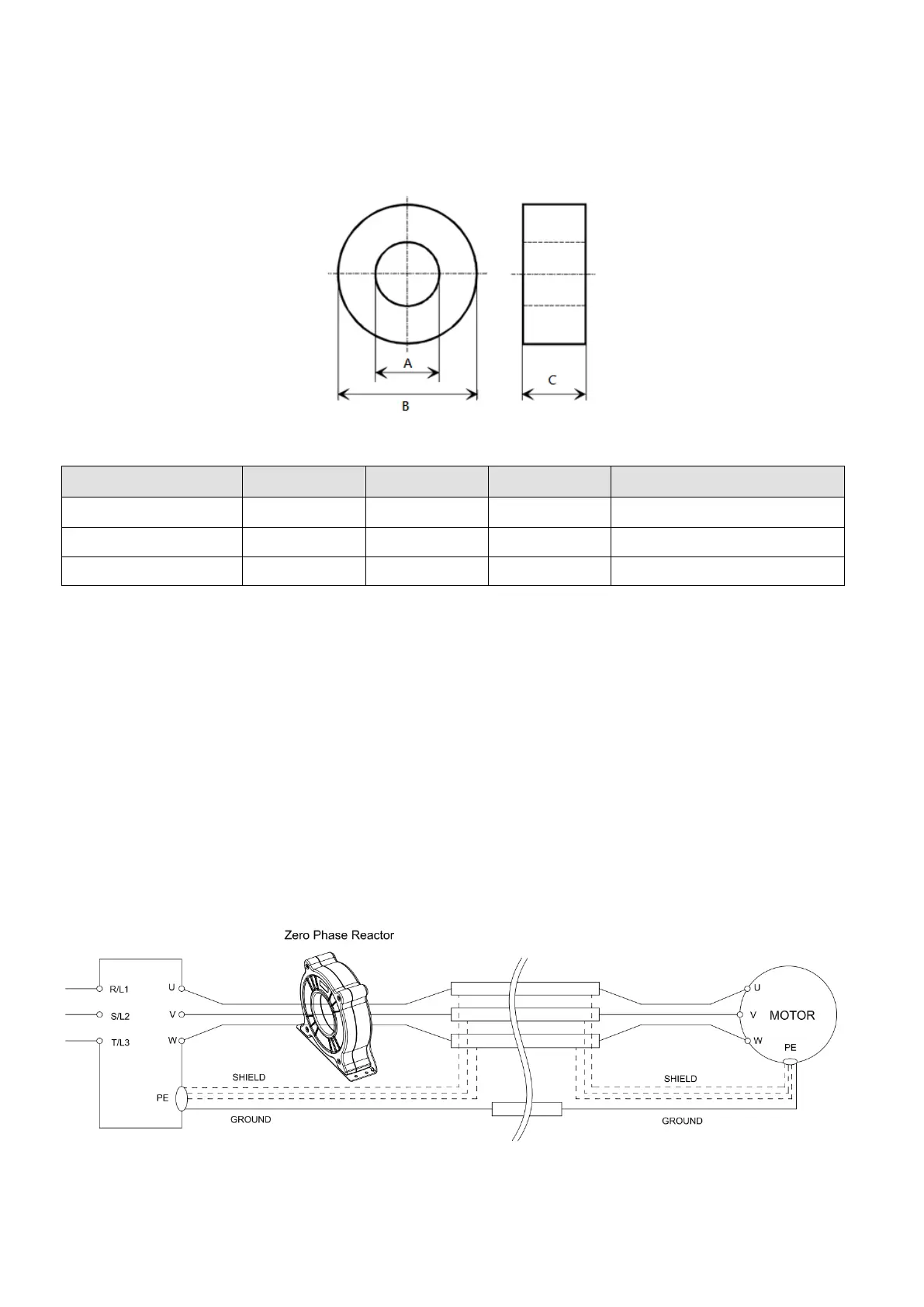
Fig. 7-30
Unit: mm
Model A B C Purpose
RF008X00N 22.5 43.1 18.5
To use with motor cable
RF004X00N 36.3 53.5 23.4 To use with motor cable
RF410X00N 108.1 70 30.3 To use with motor cable
Table 7-52
Installation
During installation, pass the cable through at least one zero-phase reactor.
Use a suitable cable type (insulation class and wire section) so that the cable passes easily through the
zero-phase reactor. Do not pass the grounding cable through the zero-phase reactor; only pass the motor
wire through the zero-phase reactor.
With longer motor cables the zero-phase reactor can effectively reduce interference at the motor
output. Install the zero-phase reactor as close to the output of the drive as possible. Figure A shows the
installation diagram for a single turn zero-phase reactor. If the wire diameter allows several turns, Figure
B shows the installation of a multi-turn zero-phase reactor. The more turns, the better the noise
suppression effect.
Figure A: Single turn wiring diagram for a shielding wire with a zero-phase reactor

 Loading...


