Chapter 7 Optional AccessoriesMH300
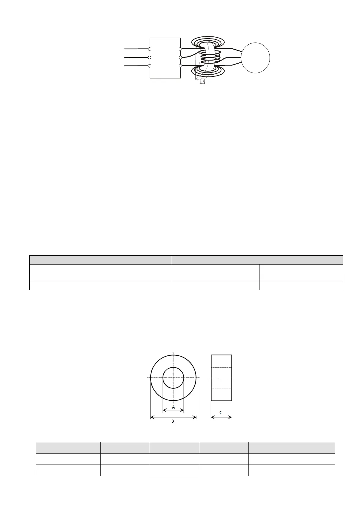
Power
Supply
Zero Phase Reactor
MOTOR
U/T1
V/T2
W/T3
R/L1
S/L2
T/L3
Figure B: Multi-turn zero-phase reactor
Installation notes
Install the zero-phase reactor at the output terminal of the frequency converter (U, V, W). After the
zero-phase reactor is installed, it reduces the electromagnetic radiation and load stress emitted by the
wiring of the frequency converter. The number of zero-phase reactors required for the drive depends on
the wiring length and the drive voltage.
The normal operating temperature of the zero-phase reactor should be lower than 85°C (176°F).
However, when the zero-phase reactor is saturated, its temperature may exceed 85°C (176°F). In this
case, increase the number of zero-phase reactors to avoid saturation. The following are reasons that might
cause saturation of the zero-phase reactors: the drive wiring is too long, the drive has several sets of loads,
the wiring is in parallel, or the drive uses high capacitance wiring. If the temperature of the zero-phase
reactor exceeds 85°C (176°F) during the operation of the drive, increase the number of zero-phase
reactors.
Recommended maximum wiring gauge when installing zero-phase reactor
RF008X00A or RF008X00N ≤ 8 AWG ≤ 8.37 mm
2
Table 7-53
Zero-phase Reactor for Signal Cable
To solve interference problems between signal cables and electric devices, install a zero-phase
reactor on the signal cable. Install it on the signal cable which is the source of the interference to
suppress the noise for a better signal. The model names and dimensions are listed in the table below.
Fig. 7-31
Unit: mm
Model A B C
Purpose
RF026X00N 10.7 17.8 8.0
To use with signal cable
RF020X00N 17.5 27.3 12.3
To use with signal cable
Table 7-54

 Loading...


