Chapter 7 Optional AccessoriesMH300
Frame G
Frame
Model
- MH300
Input
Current
(A)
Model
-EMC Filter
Model
-Zero-phase reactor
Conducted emission
cable
cable length-
cable
cable
Position to place zero-phase reactor
G
VFD75AMH23ANSAA 85 B84143A0120R105
✓
✓
✓
✓
✓
VFD90AMH23ANSAA 103 B84143A0120R105
✓
✓
✓
✓
✓
VFD60AMH43ANSAA 72.5 B84143A0120R105
✓ ✓
✓
Table 7-56
Frame H–I
Frame
Model
- MH300
Input
Current
(A)
Model
-EMC Filter
Model
-Zero-phase reactor
Conducted emission
cable
cable length-
cable
cable
Position to place zero-phase reactor
H
VFD75AMH43ANSAA 77 B84143D0150R127
✓ ✓
✓
✓
✓
VFD91AMH43ANSAA 97 B84143D0150R127
✓ ✓
✓
✓
✓
I
VFD120MH23ANSAA 126 B84143D0200R127
✓ ✓
✓
✓
✓
VFD146MH23ANSAA 151 B84143D0200R127
✓ ✓
✓
✓
✓
VFD112MH43ANSAA 123 B84143D0200R127
✓
VFD150MH43ANSAA 173 B84143D0200R127
✓
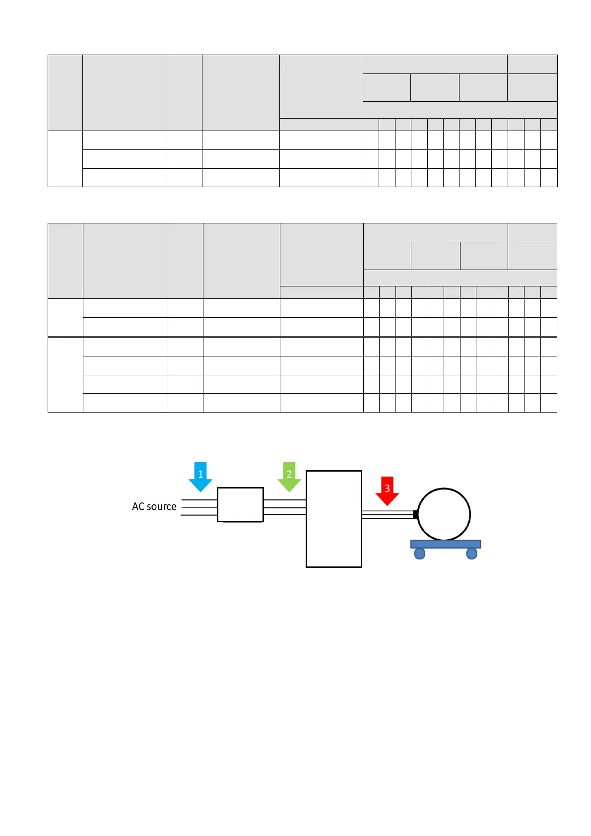
Zero-phase reactor installation position diagram:
*1 Install at the cable between the power supply and the EMC filter
*2 Install at the cable between the EMC filter and the drive
*3 Install at the cable between the drive and the motor
Filter
Drive

 Loading...


