Chapter 8 Option CardsMH300
8-10
Frame E–I
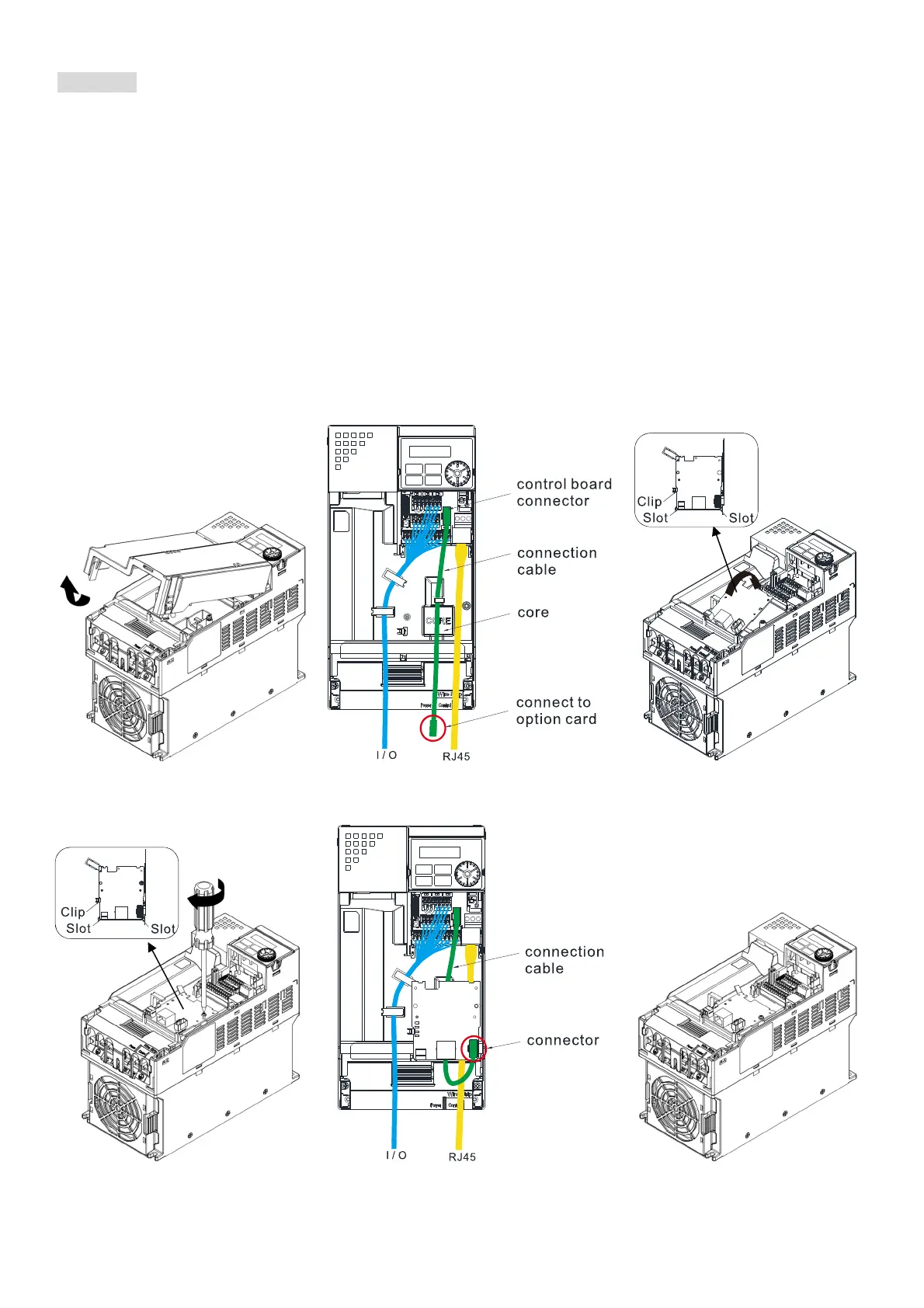
1. As shown in the Figure 8-32, shut down the power of the motor drive and then remove the front cover.
2. Assembling connection cables: Connect the connector at one end of the connection cable to the
control board connector. For information on connection method, refer to Section 8-1 (see Table 8-2
and Figure 8-3). Wire them as Figure 8-33 shows and make sure the core place in the groove.
3. Assembling option cards: Place the terminal block and connector of the option card upward. Fix the
front end of the option card to the slots, and then press another side, as shown in the Figure 8-34.
4. Make sure that clips are properly engage the option card, and then fasten the screws [Suggested
torque value: 4–6 kg-cm / (3.5–5.2 lb-in.) / (0.39–0.59 Nm)], as shown in the Figure 8-35.
5. Assembling connection cables: Connect the connector at the other end of the connection cable to the
connector of option cards, as shown in the Figure 8-36.
6. As shown in the Figure 8-37, assembly is completed.
Figure 8-32 Figure 8-33 Figure 8-34
Figure 8-35 Figure 8-36 Figure 8-37

 Loading...


