Chapter 8 Option CardsMH300
8-11
NOTE:
You must ground the option cards listed below when wiring. The ground terminal is included with
option card as shown in Figure 8-38
1. CMM-PD02 7. EMM-PG01L
2. CMM-DN02 8. EMM-PG01O
3. CMM-EIP02 9. EMM-PG01R
4. CMM-EIP03 10. EMM-A22A
5. CMM-EC02 11. EMM-D33A
6. EMM-BPS02
Figure 8-38
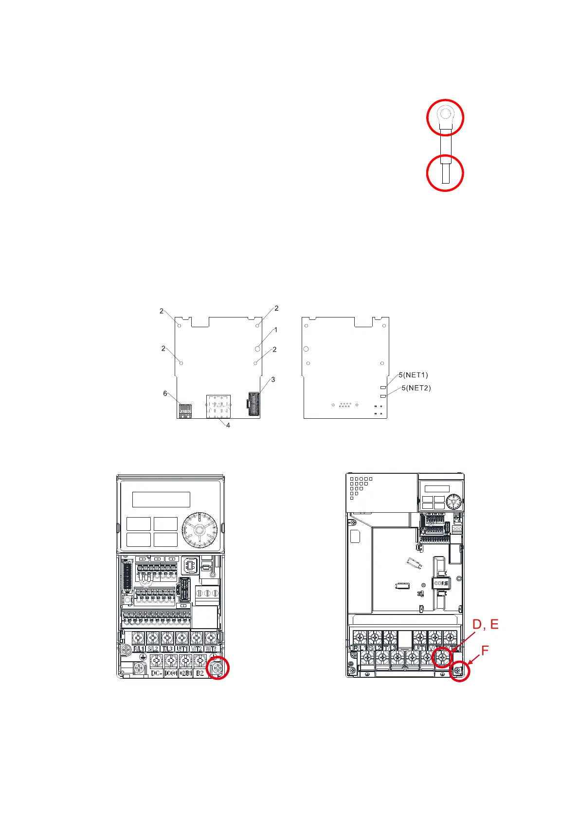
Installation of the ground terminal:
The B side of the ground terminal connects to the ground terminal block on the communication card at
No.6 of the CMM-EIP02 shown in Figure 8-39. See each section in Chapter 8 for the ground terminal
blocks of the other option cards. The A side of the ground terminal connects to the PE on the drive as the
red circles show in Figure 8-40 and 8-43.
Figure 8-39
Frame A–C Frame D–F
Figure 8-40 Figure 8-41
Torque (±10%)
Frame A: 9 kg-cm / (7.8 Ib-in.) / (0.88 Nm)
Frame B: 15 kg-cm / (13.0 Ib-in.) / (1.47 Nm)
Frame C: 20 kg-cm / (17.4 Ib-in.) / (1.96 Nm)
Torque (±10%)
Frame D: 20 kg-cm / (17.4 Ib-in.) / (1.96 Nm)
Frame E: 25 kg-cm / (21.7 Ib-in.) / (2.45 Nm)
Frame F: 20 kg-cm / (17.4 Ib-in.) / (1.96 Nm)
Point A
Point B

 Loading...


