Chapter 9 Specification
MH300
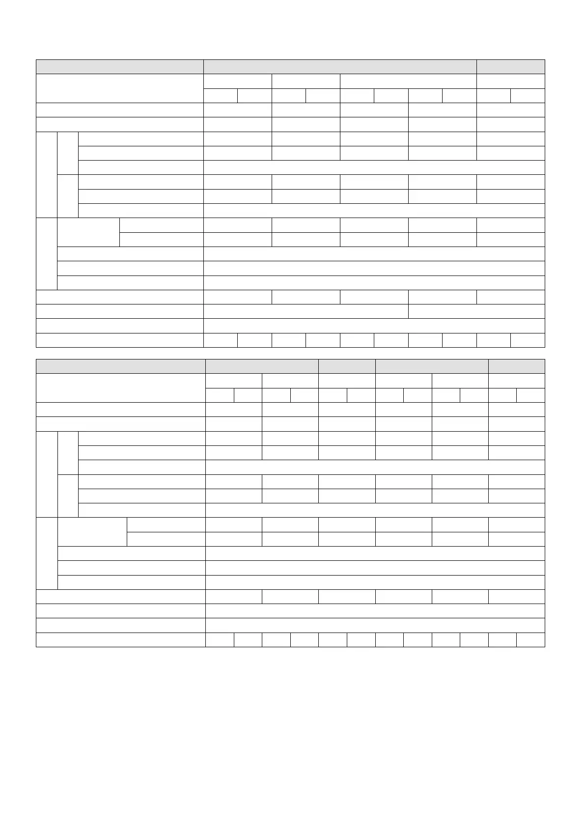
230V, three-phase
Frame A B
Model VFD_ _ _ _ _ _ _ _ _ _ _A
_ _
5A0MH23_ _ _ _ 7A5MH23_ _ _ _
ANSA ENSA ANSA ENSA ANSN ENSN ANSA ENSA ANSA ENSA
Applicable Motor Output (kW) 0.2 0.4 0.75 0.75 1.5
Applicable Motor Output (HP) 0.25 0.5 1 1 2
*1
Rated Output Capacity (kVA) 0.6 1.9 1.9 1.9 2.9
Carrier Frequency (kHz)
*2
2–15 (Default: 4)
Rated Output Capacity (kVA) 0.7 1.2 2.0 2.0 3.0
Rated Output Current (A) 1.8 3.2 5.2 5.2 8.0
Carrier Frequency (kHz)
*2
2–15 (Default: 4)
Rated Input
Current (A)
Heavy Duty 1.9 3.4 6.0 6.0 9.0
Normal Duty 2.2 3.8 6.2 6.2 9.6
Rated Voltage / Frequency Three-phase, 200–240 V
AC
(-15%– +10%), 50 / 60 Hz
Operating Voltage Range (V
AC
) 170–265
Frequency Range (Hz) 47–63
Weight (kg) 0.76 0.76 0.81 0.77 1.05
Cooling Method Convective cooling Fan cooling
Ingress Protection Rating IP20 IP40
*3
IP20 IP40
*3
IP20 IP40
*3
IP20 IP40
*3
IP20 IP40
*3
Frame C D E F
Model VFD_ _ _ _ _ _ _ _ _SAA
AN EN AN4 EN AN EN AN EN AN EN AN EN
Applicable Motor Output (kW) 2.2 3.7 5.5 7.5 11 15
Applicable Motor Output (HP) 3 5 7.5 10 15 20
*1
Rated Output Capacity (kVA) 4.2 6.5 9.5 12.6 18.7 24.8
Carrier Frequency (kHz)
*2
2–15 (Default: 4)
Rated Output Capacity (kVA) 4.8 7.4 10.3 13.7 19.4 26.3
Rated Output Current (A) 12.5 19.5 27.0 36.0 51.0 69.0
Carrier Frequency (kHz)
*2
2–15 (Default: 4)
Rated Input
Current (A)
Heavy Duty 13.2 20.4 30.0 39.6 58.8 78.0
Normal Duty 15.0 23.4 32.4 43.2 61.2 82.8
Rated Voltage / Frequency three-phase, 200–240 V
AC
(-15 %– +10 %), 50 / 60 Hz
Operating Voltage Range (V
AC
) 170–265
Frequency Range (Hz) 47–63
Weight (kg) 1.24 1.24 2.07 3.97 3.97 6.30
Cooling Method Fan cooling
Ingress Protection Rating IP20 IP40
*3
IP20 IP40
*3
IP20 IP40
*3
IP20 IP40
*3
IP20 IP40
*3
IP20 IP40
*3
Table 9-3
NOTE:
1. The default is heavy duty mode.
2. The value of the carrier frequency is set in the factory. To increase the carrier frequency, decrease the current.
See the derating curve diagram in Section 9-6.
3. The IP rating of the wiring area (main circuit terminals and control terminals, frame A / B / C / D / E / F) and the
vent near the capacitor (frame C / D / E / F) is IP20.
4. When the load is a shock or impact load, use a higher level model.

 Loading...


