Chapter 12 Descriptions of Parameter Settings
MH300
Explanation 1
When Pr.10-01 is set to 1000 and Pr.10-02 is set to 1, 2, the displayed range for PG feedback is
between 0–4000.
When Pr.10-01 is set to 1000 and Pr.10-02 is set to 3, 4, 5, the displayed range for PG feedback is
between 0–1000.
Explanation 2
It can also display negative values when setting analog input bias (Pr.03-03–03-10).
Example: Assume that AVI input voltage is 0 V, Pr.03-03 is 10.0%, Pr.03-07 is 4 (Bias serves as the
center).
Explanation 3
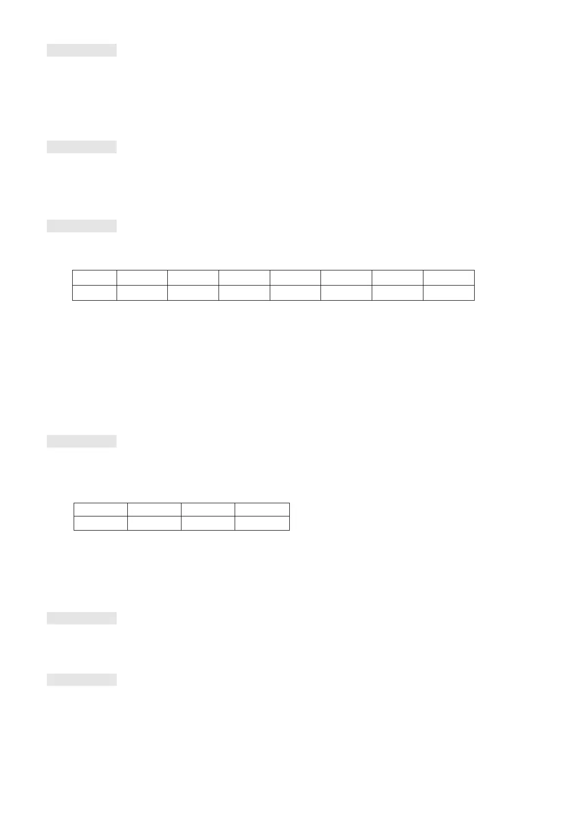
Example: If MI1 and MI6 are ON, the following table shows the status of the terminals.
Normally opened contact (N.O.): (0: OFF, 1: ON)
The value is 0000 0000 0010 0001 in binary and 0021H in HEX. When Pr.00-04 is set to 16 or 19,
the u page on the keypad displays 0021h.
The setting 16 is the ON / OFF status of digital input according to Pr.02-12 setting and the setting 19
is the corresponding CPU pin ON / OFF status of the digital input.
When MI1 / MI2 default setting is two-wire/ three-wire operation control (Pr.02-00 ≠ 0), and MI3 is set
as three-wire, it is not affected by Pr.02-12.
You can set 16 to monitor the digital input status, and then set 19 to check if the circuit is normal.
Explanation 4
Example: Assume that RY: Pr.02-13 is set to 9 (Drive is ready). After the drive is powered on, if there
is no other abnormal status, the contact is ON. The display status is shown below.
Normally opened contact (N.O.):
If Pr.00-04 is set to 17 or 20, it displays in hexadecimal “0001h” with LED u page is ON in the keypad.
The setting 17 is the ON / OFF status of digital output according to Pr.02-18 setting and the setting
20 is the corresponding CPU pin ON / OFF status of the digital output.
You can set 17 to monitor the digital output status, and then set 20 to check if the circuit is normal.
Explanation 5
Setting value 8: 100% means the motor rated torque.
Motor rated torque = (motor rated power x 60 / 2π) / motor rated rotating speed
Explanation 6
Setting value 25: when displayed value reaches 100.00%, the drive shows “oL” as an overload
warning.

 Loading...


