Chapter 12 Description of Parameter Settings
MH300
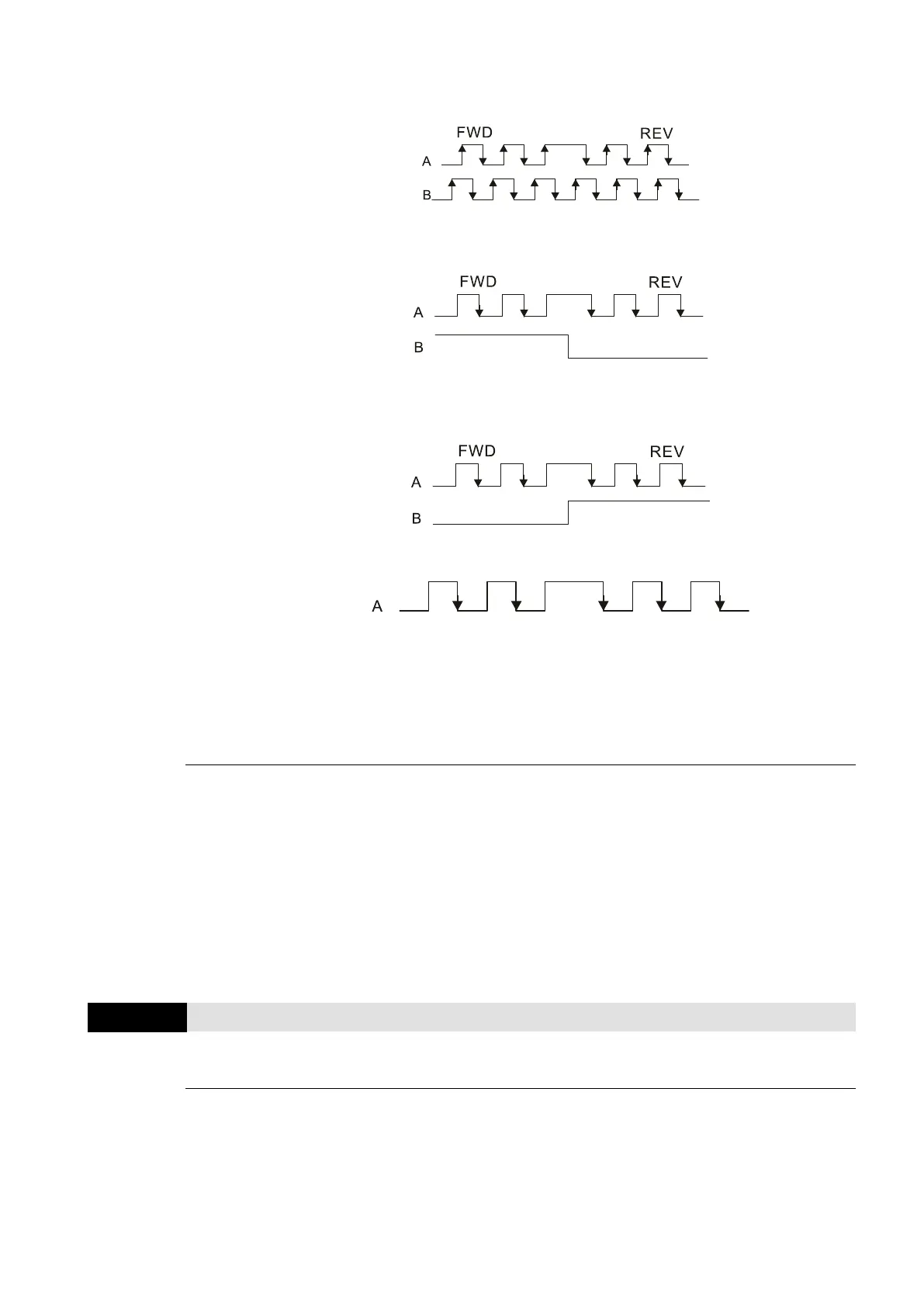
2: Phases A and B are pulse inputs, forward direction if B-phase leads A-
phase by 90 degrees
.
3: Phase A is a pulse input and phase B is a direction input (low input =
reverse direction, high input = forward direction).
4: Phase A is a pulse input and phase B is a direction input (low input =
forward direction, high input = reverse direction).
5: Single-phase input (MI7)
NOTE:
1: When the MH300 inputs the A /
B phase pulse, you must connect the MI6
terminal to the A-phase pulse, and the MI7 terminal to the B-phase pulse.
2: When the MH300 uses single-phase input, it disables the MI6 function and
prohibits any signal connection.
Velocity control: PG2 acts according to the setting for Pr.10-01 (PG1 ppr), and will not be affected
by PG1 pulse (single-phase pulse or A / B phase pulse). When the setting for Pr.10-00, Pr.10-01
and Pr.10-02 are changed, cycle the power of the motor drive.
1. The speed formula is (input ppr) / (PG1 ppr), when PG1 ppt = 2500, PG2 is single-phase
pulse, and the input pps is 1000 (1000 pulse per second), the speed should be
(1000 / 2500) = 0.40 Hz.
2. The same pps inputs of A / B phase pulse or single-phase pulse input should get the same
frequency command.
Frequency Division Output Setting (Denominator)
Default: 1
Settings 1–255
Sets the denominator for the frequency division of the PG card feedback and output. When you
set it to 2 with feedback 1024 ppr, PG OUT (pulse output) of PG card is 1024 / 2 = 512 ppr.

 Loading...


