Chapter 12 Description of Parameter Settings
MH300
Electrical Gear at Load Side A1
Electrical Gear at Motor Side B1
Electrical Gear at Load Side A2
Electrical Gear at Motor Side B2
Default: 100
Settings 1–65535
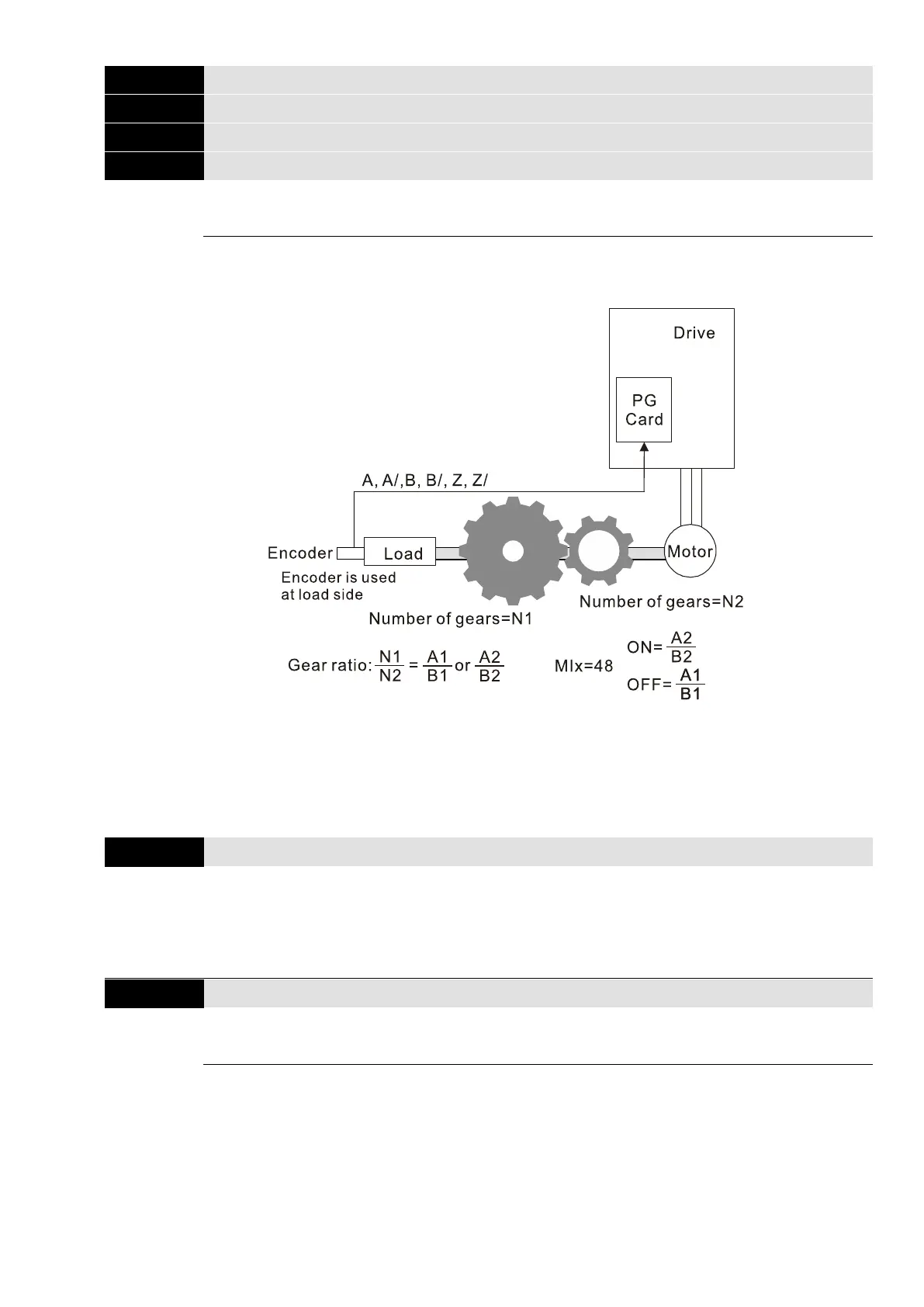
Use Pr.10-04–10-07 with the multi-function input terminal setting 48 to switch to Pr.10-04–10-05 or
Pr.10-06–10-07, as shown in the diagram below.
A1 = Mechanical Gear A1 at Load Side (Pr.10-04)
B1 = Mechanical Gear B1 at Motor Side (Pr.10-05)
A2 = Mechanical Gear A2 at Load Side (Pr.10-06)
B2 = Mechanical Gear B2 at Motor Side (Pr.10-07)
Encoder Feedback Fault Treatment
Default: 2
Settings 0: Warn and continue operation
1: Fault and ramp to stop
2: Fault and coast to stop
Encoder Feedback Fault Detection Time
Default: 1.0
Settings 0.0–10.0 sec. (0: disabled)
When there is an encoder loss, an encoder signal error, a pulse signal setting error or a signal
error, if the duration exceeds the detection time for the encoder feedback fault (Pr.10-09), the
encoder signal error occurs. Refer to Pr.10-08 for encoder feedback fault treatment.
When the speed controller signal is abnormal, if time exceeds the detection time for the encoder
feedback fault (Pr.10-09), the feedback fault occurs. Refer to Pr.10-08 for the encoder feedback
fault treatment.

 Loading...


