Stacker
Service Instructions 745-35-10 S/745-35-10 A - 02.0 - 04/2017 161
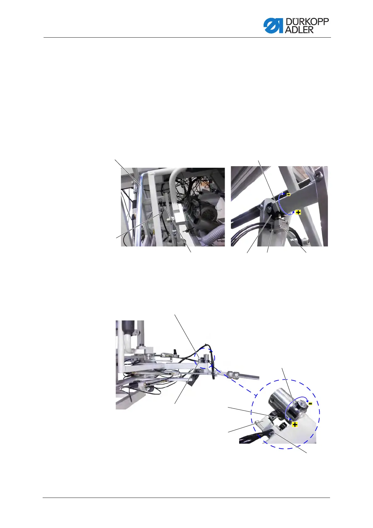
2. Valve 1 (2) is pressed into the lower end position.
Clamping bracket b (4) is lifted.
Switch cam c (3) that operates valve 1 (2) needs to be set such that
swivel bracket a (5) safely clamps the sewing material before clamp-
ing bracket b (4) is lifted.
3. Loosen the screw on switch cam c (3) and turn switch cam c (3) on the
axle.
• Switch actuation point later (+): turn counterclockwise
• Switch actuation point earlier (-): turn clockwise
Fig. 141: Checking the function sequence (2)
Fig. 142: Checking the function sequence (3)
(1) - Throw-over bracket d
(6) - Valve 2
(7) - Valve 4
(8) - Switch cam e
(9) - Switch cam i
(10) - Valve 5
(11) - Valve 3
(12) - Switch cam g
(13) - Switch cam h
 Loading...