Machine head
48 Service Instructions 745-35-10 S/745-35-10 A - 02.0 - 04/2017
5. Shift the worm wheel (2) in axial direction.
The distance between the worm wheel (2) and the inner side of the
hook housing must be 0.3 mm. At the right hook housing the distance
must be on the right of the worm wheel and at the left hook housing
on the left of the worm wheel.
6. Measure the distance using a feeler gage.
7. Set the gear clearance by turning the socket (4).
While it should be as low as possible, the gear clearance between
worm and worm wheel should be noticeable.
• To increase the gear clearance: Turn the socket (4) upward.
• To reduce the gear clearance: Turn the socket (4) downward.
8. Check and, if necessary, correct the loop stroke ( p. 48) and the
distance of the hook tip to the needle ( p. 52).
9. Tighten screws (1) and (3).
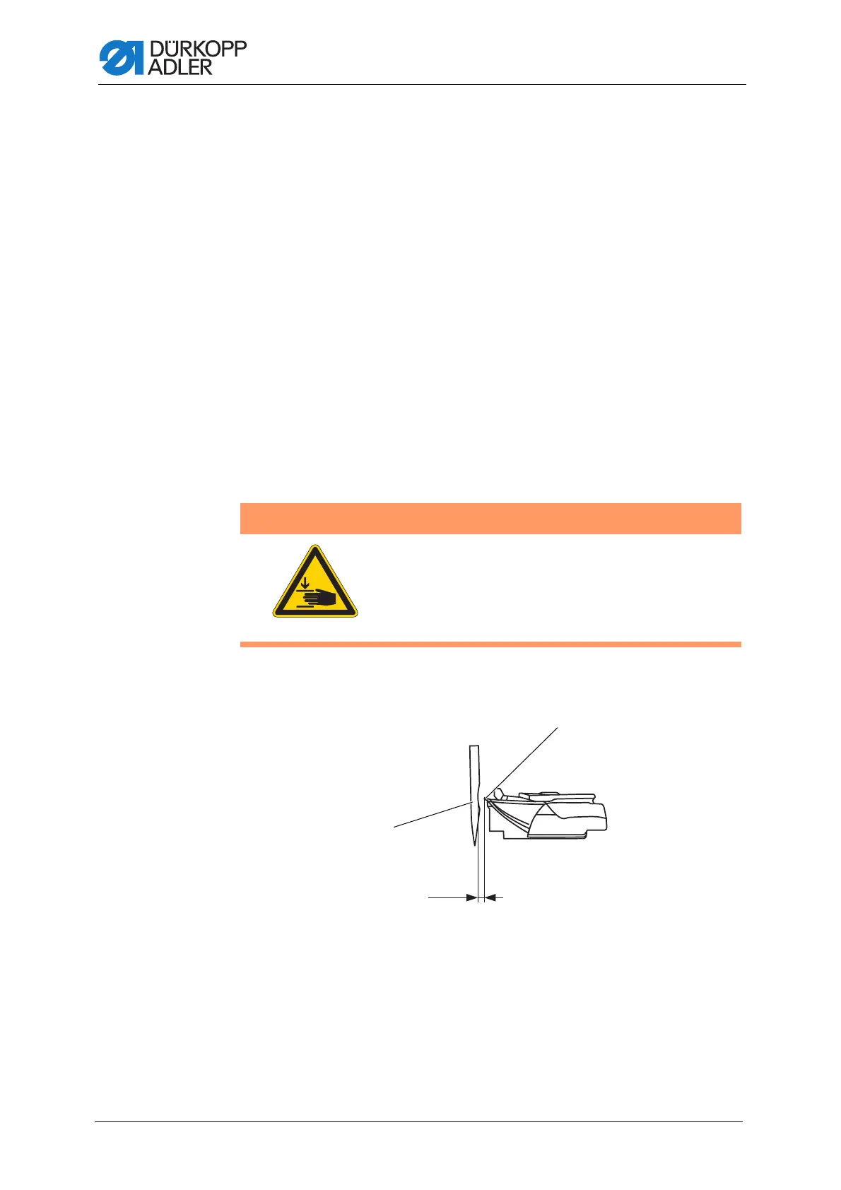
3.9.3 Setting the loop stroke
Fig. 36: Setting the loop stroke (1)
WARNING
Risk of injury from moving parts!
Crushing possible.
Do not check and adjust the loop stroke unless the
sewing unit is switched off.
(1) - Needle (2) - Hook tip
0,1 mm
 Loading...