Transport carriage
76 Service Instructions 745-35-10 S/745-35-10 A - 02.0 - 04/2017
The distance between the switching screw (2) and the reference switch (1)
must range between 0.5 mm and 1 mm.
Once the transport carriage has returned so far that the switching screw
(2) is positioned in the center below the reference switch (1), the distance
between transport carriage (3) and stop (4) must be 2 mm.
The fine adjustment is made during the setting of the transport clamp
( p. 85). This adjustment also requires a correction of the stop.
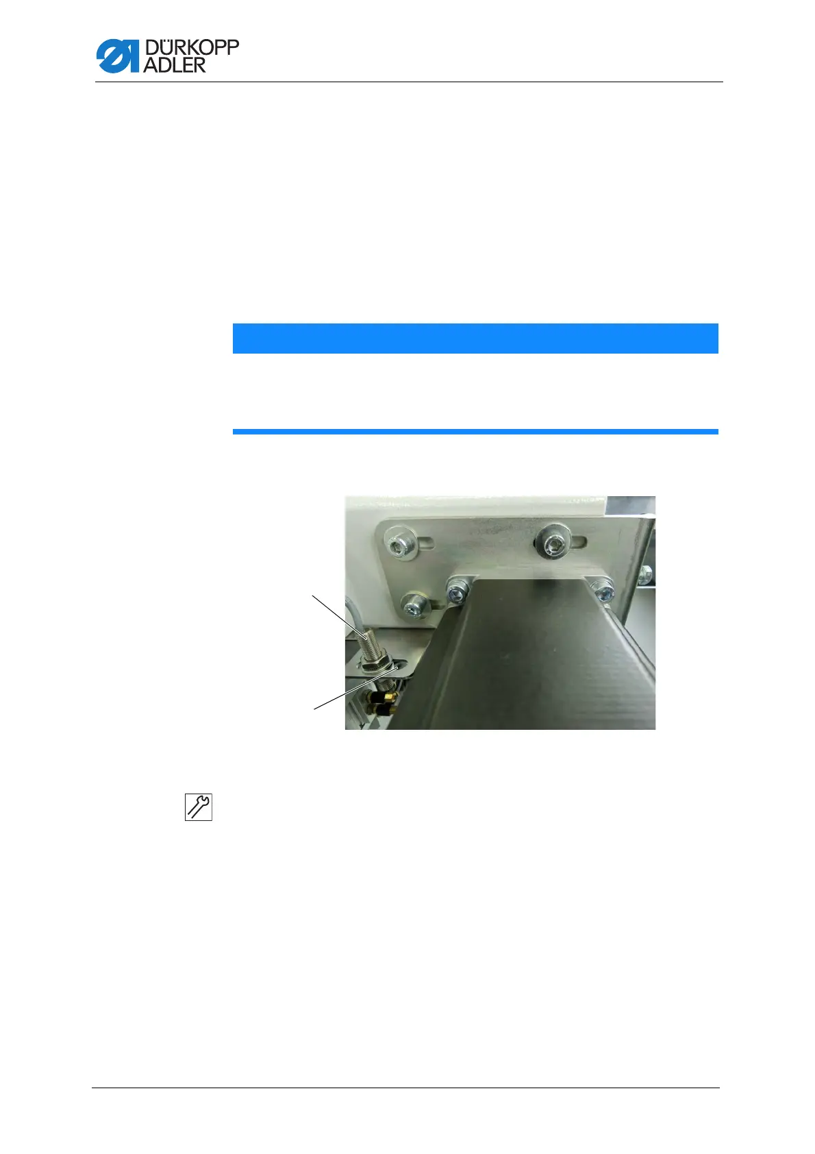
4.1.1 Setting the position of the reference switch in the slotted hole
Fig. 63: Position of the reference switch in the slotted hole
To set the position of the reference switch in the slotted hole:
1. Loosen the upper counternut at the reference switch (1).
2. Adjust the reference switch in the slotted hole (2) ( p. 92).
3. Re-tighten the upper counternut.
NOTICE
Property damage may occur!
Collision and functional failure of the machine.
Check the distance between reference switch and switching screw.
(1) - Reference switch (2) - Slotted hole
 Loading...