Machine head
26 Service Instructions 745-35-10 S/745-35-10 A - 02.0 - 04/2017
To remove switching cylinder and needle bar linkage:
1. Remove needle bar linkage (7) ( p. 38).
2. Remove the switching cylinder (6) used for the middle knife drive
( p. 61).
Assembling the crank pin
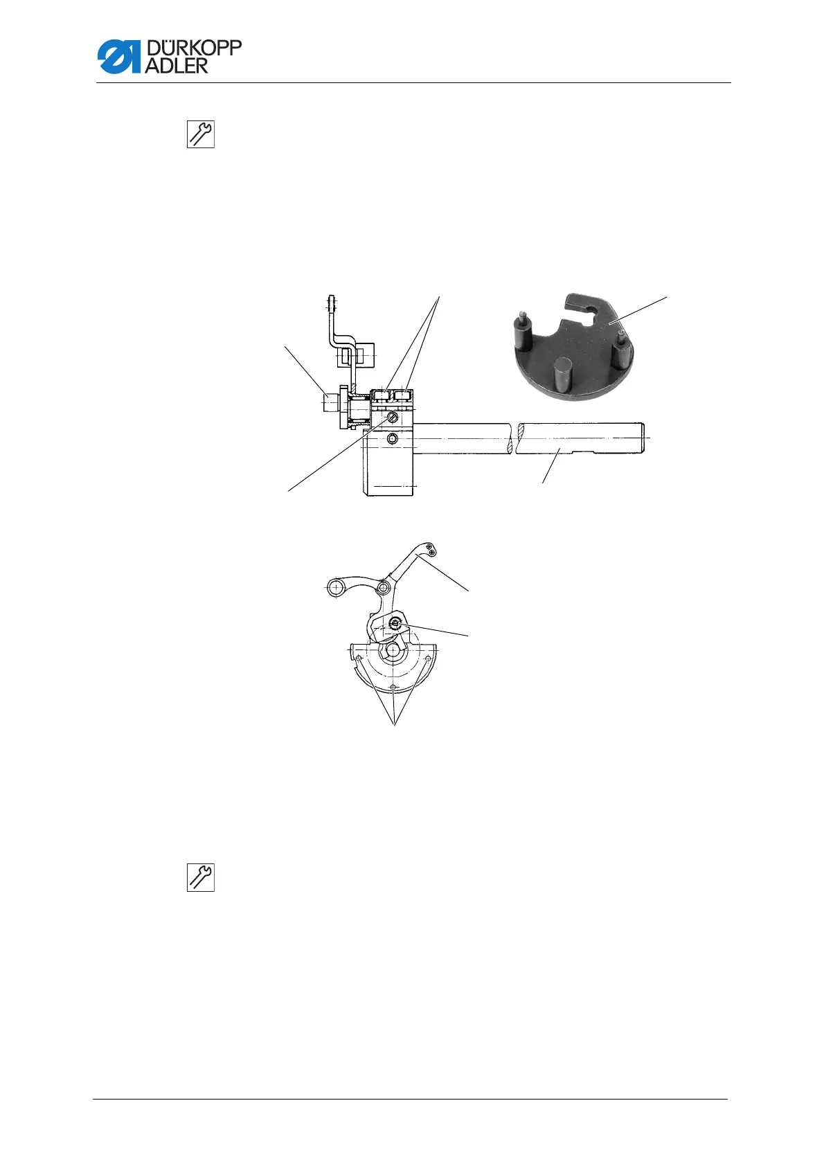
Fig. 15: Assembling the crank pin
To assemble the crank pin:
1. Loosen the fastening screws (Caution: Left-handed thread).
2. Loosen the needle bar connecting rod from the crank pin (8) and pull
it off along with the needle cage.
3. Turn the handwheel until the hexagon screws (14) are facing down.
In this position, the screws are accessible.
4. Loosen the hexagon screws (14).
5. Loosen the screw (9). The screw can be accessed through the hole (3)
(figure above).
(8) - Crank pin
(9) - Screw
(10) - Locating bore
(11) - Thread lever
(12) - Arm shaft
(13) - Gage
(14) - Hexagon screws
 Loading...