Only one of these can have control of the dry pumping system at any one me. That is,
once one of these has control of the dry pumping system, the control requests from the
others are denied. Control must be released by one module before it can be taken by a
dierent module.
There are LEDs to indicate control:
▪ The LED on the front control panel illuminates when control is taken by the front
panel. Refer to Figure: Front panel controls, item 6.
▪ The LED on the rear of the pump illuminates when control is taken by the
MicroTIM. Refer to Figure: The controls/connectors on the rear of the pump
(system with rear exhaust and castors/levelling feet ed), item 9.
▪
The local control LED on the PDT illuminates when control is taken by that
parcular PDT. Refer to Pump display terminal on page 120.
The PDT display also indicates which system is in control.
1.5 Acve ulity control/standby
The acve ulity control (Green mode) funcon may reduce the speed, power and purge
gas consumpon of the dry pumping system while on standby. The dry pumping system
can be put into Green mode/Standby mode using the front control panel, the PDT or
through the MCM MicroTIM. Refer to Green mode/standby mode on page 57 for more
informaon.
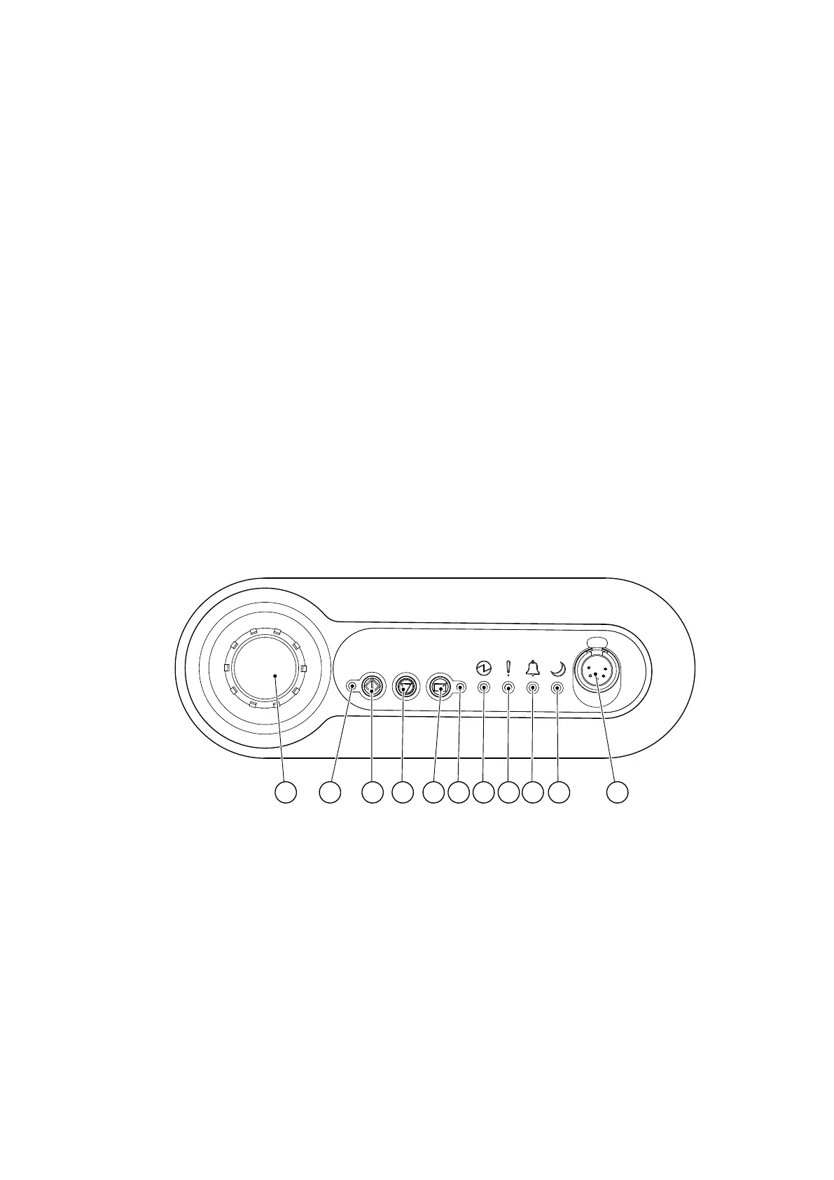
Figure 1 Front panel controls
1 2 119876543 10
CS/1059/A
1. EMS buon 2. Running LED (green)
3. Start buon 4. Stop buon
5. Local control buon 6. Local control LED (green)
7. Power LED (green) 8. Warning LED (amber)
9. Alarm LED (red) 10. Green mode LED (green)
11. Pump Display Terminal (PDT) connecon
1. EMS buon 2. Running LED (green)
3. Start buon 4. Stop buon
5. Local control buon 6. Local control LED (green)
7. Power LED (green) 8. Warning LED (amber)
9. Alarm LED (red) 10. Green mode LED (green)
11. Pump Display Terminal (PDT) connecon
Page 12
M58800880_H - Introducon

 Loading...


