(refer to Pump display terminal on page 120). The PDT is available as an accessory. Refer
to Accessories on page 77.
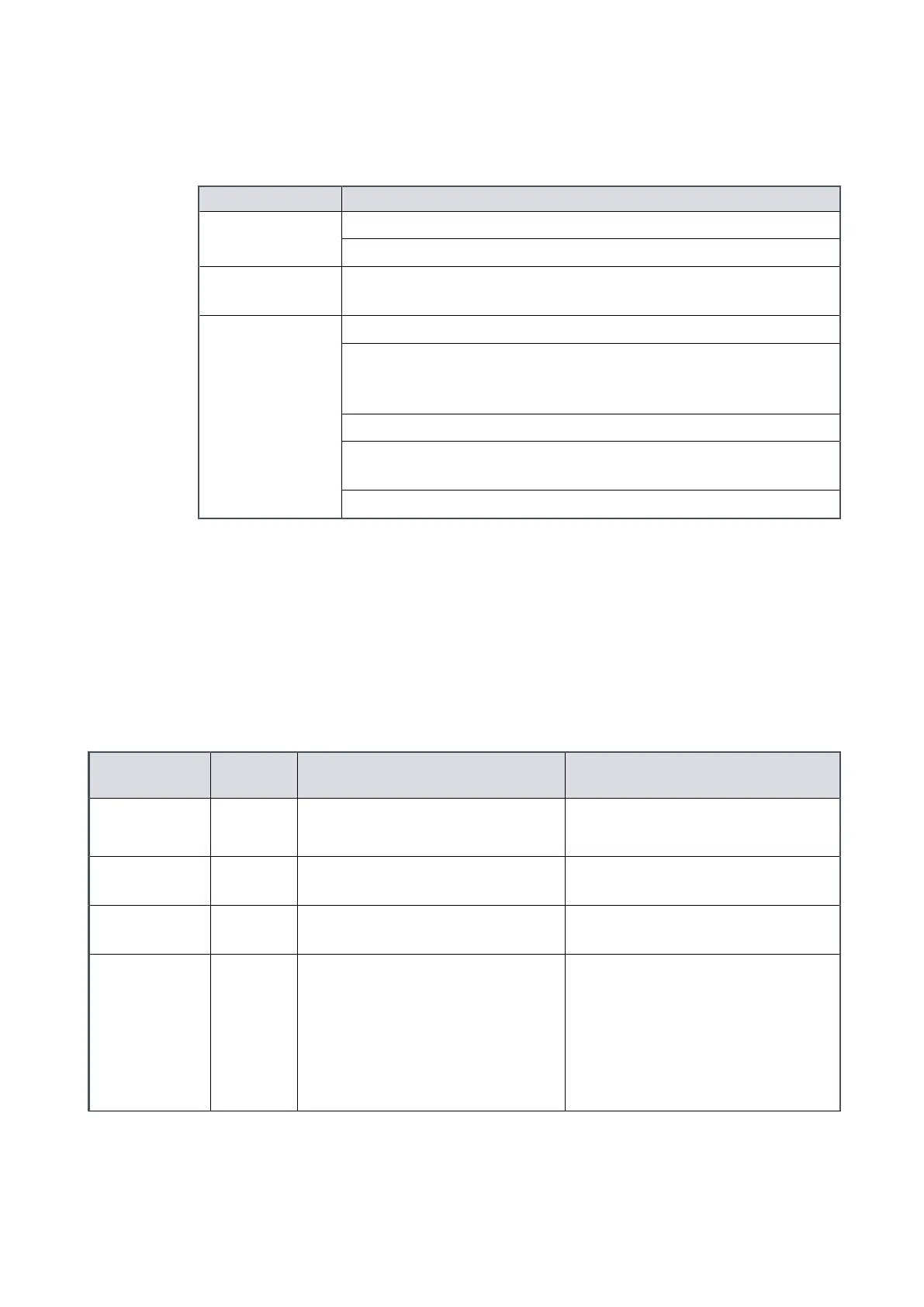
Table 18
Start, warm-up and on-process sequences
Sequence Descripon
Start pump
Sha Seal Purge (SSP) valve is opened.
Pump runs.
Warm-up
Pump runs at 110 Hz unl it reaches the working temperature and
then goes on‑process (default auto on-process).
On-process
Inlet isolaon valve opened (if ed).
Pump speed from the standby (Green mode) to full speed may be
ramped by congurable increments instead of going straight to full
speed.
Pump will not go on-process if there are acve warnings.
Pump may be congured to ignore warnings and go straight onto
process.
Gas ballast is opened (if ed, medium‑duty pumps only).
4.2 Status indicators
The dry pumping system has a number of LEDs that indicate pump status. The status
LEDs are found:
▪ on the front panel controls. Refer to Figure: Front panel controls
▪
on the rear panel. Refer to Figure: The controls/connectors on the rear of the pump
(system with rear exhaust and castors/levelling feet ed).
Table 19
Status indicator LEDs
Indicator
Name
LED
colour
Locaon Meaning
Power Green Front panel (item 7)
Rear panel (item 4)
Illuminates connuously when the
system has power.
Front panel
control
Green Front panel (item 6) Illuminates connuously to indicate
the front panel is 'in control'.
Tool control Green Rear panel (item 9) Illuminates connuously to indicate
the MCM MicroTIM is 'in control'.
Pump running Green Front panel (item 2)
Rear panel (item 7)
Illuminates connuously when the
pump is running on‑process.
Flashes to indicate that the pump is
warming up, shung down or in
Green mode/standby mode. Refer
to Determining the pump status on
page 57.
Page 56
M58800880_H - Operaon

 Loading...


