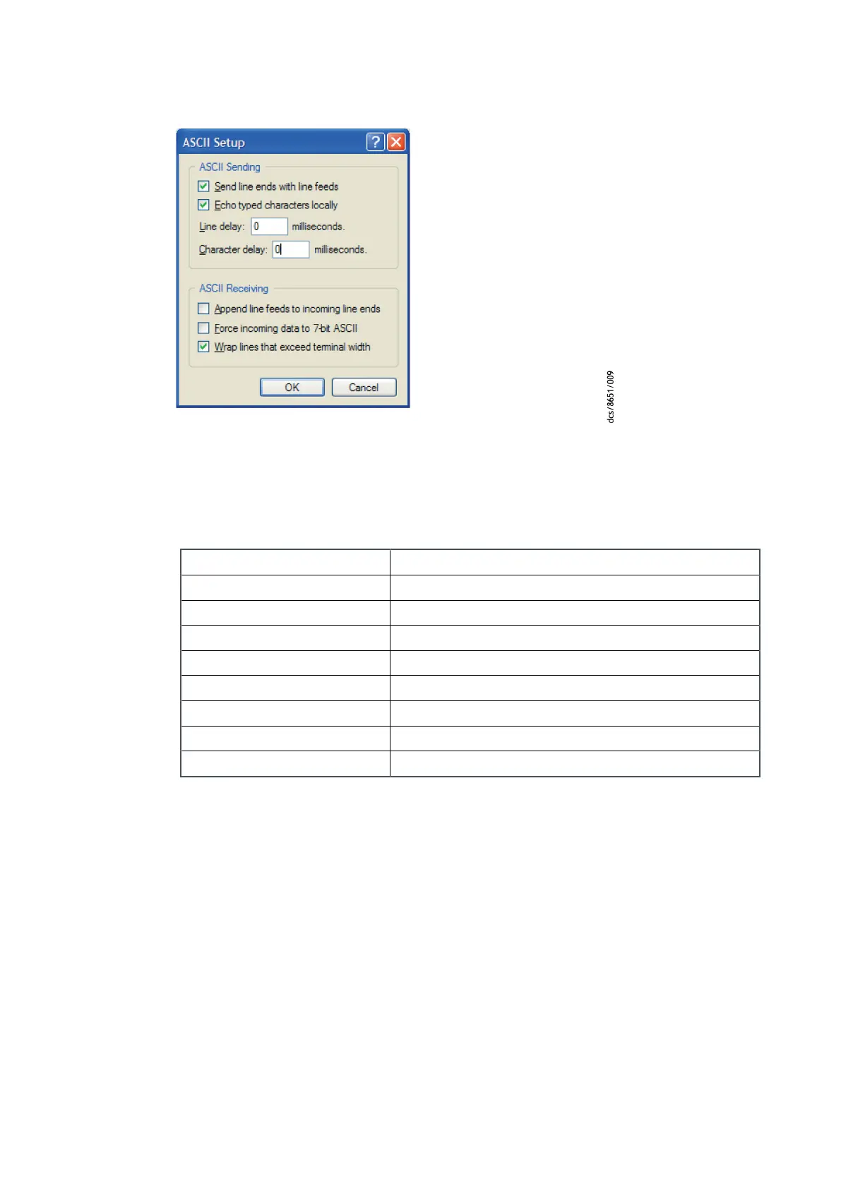
Figure 74 ASCII sengs screenshot
In the HyperTerminal window, type: '?T' and press the ENTER key.
If successful, you should get a reply with the following format:
157,28,19,42,0,72,121,35,0
In this example:
157 indicates the pump controller
28 indicates the GXS pump family
19 indicates the GXS250
42 indicates the GXB2600 booster
0 indicates the GXS screw pump
72 indicates low volts, 7.5 kW DP and 7.5 kW BP
121 indicates a harsh gas module
35 indicates a normal thermal management type
0 indicates a normal exhaust type
Refer to the SIM manual for more informaon about the various eld elements and
what they mean for the system. Any other query and command can be sent by typing
the operaon and parameter followed by the ENTER key.
9.14 How to set up the MCM MicroTIM using the PDT
If the MCM MicroTIM is ed to the system, all the pump conguraon sengs that are
made using the PDT are automacally stored in the MicroTIM. This means that if a new
system is ed, for example, while servicing the exisng system, there is no need to
congure the new pump sengs if the original MicroTIM is used.
The PDT can also be used to congure the channel 2 input and channel 4 output on the
MCM MicroTIM itself. Refer to the MicroTIM instrucon manual D37360880 for full
informaon about MicroTIM installaon and setup.
The following menus are used by the PDT to congure the MCM MicroTIM channel 2
input and channel 4 output.
Page 156
M58800880_H - Pump display terminal

 Loading...


