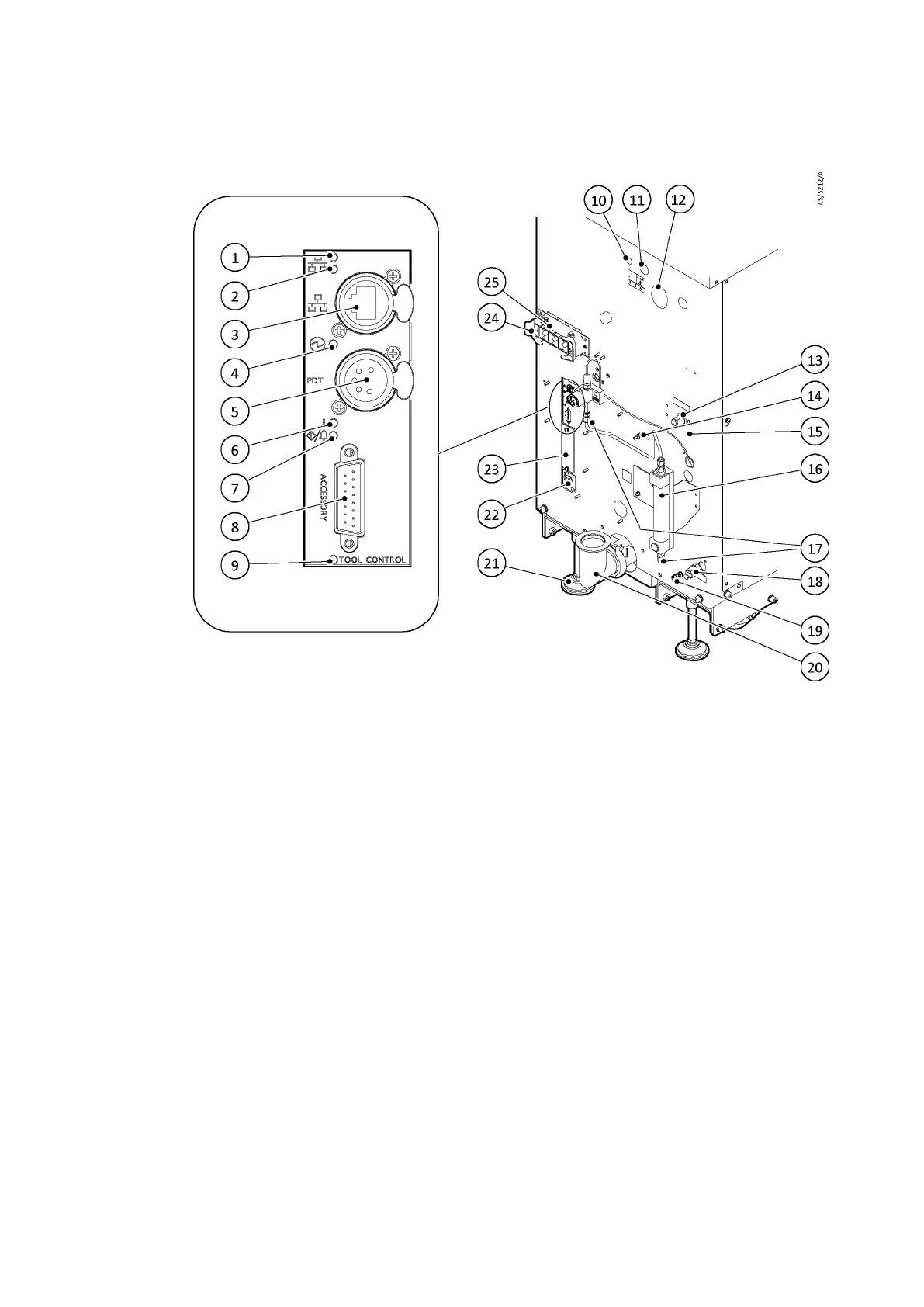
Figure 3 The controls/connectors on the rear of the pump (system with rear exhaust and castors/
levelling feet ed)
1. Ethernet LAN LED (green) 2. Ethernet link LED (yellow)
3. Ethernet connecon 4. Power LED (green)
5. System interface (PDT and serial SIM) 6. Waring LED (yellow)
7. Running and alarm LEDs (2 colours,
either green or red)
8. Accessory interface
9. Micro TIM in control LED (green)
10. Pneumac valve inlet connecon (if
ed)
11. DP clean solvent ush uid connecon (if
ed)
12. High ow purge air lter (if ed) 13. Cooling water in
14. Auxiliary gauge or pressure input
connecon (if ed)
15. Protecve earth (ground) stud
16. Purge gas rotameter (oponal)
17. Purge gas connecon 18. Cooling water out
19. RF earth (ground) stud 20. Exhaust gas outlet connecon
21. Levelling foot (if ed) 22. EMS interface
23. Micro TIM connecons (if ed) 24. Electrical supply connector
25. Electrical connector locking mechanism
Page 14
M58800880_H - Introducon

 Loading...


