2. For minimum water consumpon, regulate the cooling water ow to the dry pumping
system.
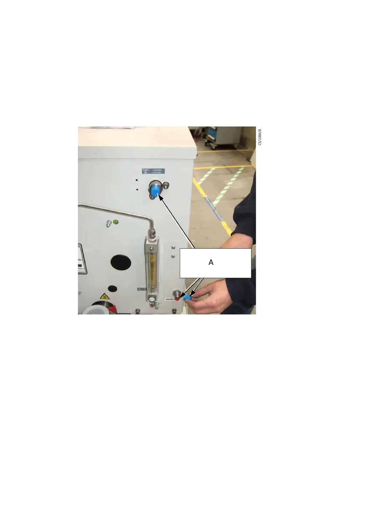
The dry pumping system is supplied with blue plasc dust caps ed over the outside of
the water inlet and outlet ngs and with red plasc plugs ed inside these water
ngs. Ensure that both sets of plasc plugs are removed before connecng the cooling
water hoses. Refer to Figure: Remove the plasc plugs from the water ngs. Retain the
plasc plugs for future use.
Figure 12 Remove the plasc plugs from the water ngs
A. Remove outer (blue) caps and inner (red)
plasc plugs
A. Remove outer (blue) caps and inner (red)
plasc plugs
*oponal nitrogen ow meter is shown in the image.
Fit the inlet strainer and then use the following procedure to connect the cooling water
supply and ensure that the dry pumping system is receiving the correct water ow rate.
Before starng, ensure that the electrical power supply to the dry pumping system is
switched o.
1.
Use BSP pipe ngs (not supplied) to t to the cooling water supply and return
hoses.
2.
Connect the water return hose to the cooling water outlet (refer to Figure: The
controls/connectors on the rear of the pump (system with rear exhaust and
castors/levelling feet ed) item 17). Fit a water ow meter into the water supply
line close to the pump and then connect the water supply hose to the cooling
water inlet (refer to Figure: The controls/connectors on the rear of the pump
(system with rear exhaust and castors/levelling feet ed), item 13). Take care not
to turn the bulkhead ngs on the pump when ghtening up the connectors.
3.
Turn on the cooling water supply.
Page 47
M58800880_H - Installaon

 Loading...


