Part 2: Maintenance 6. Replacing the Reduction Gear Units
137
(7) Secure the motor to the reduction gear unit with four bolts (M4×15 for the ES series;
M5×15 for the EL series). Be sure that the motor cable is at the opposite side of the
joint label on the reduction gear flange when secured.
(8) Mount the reduction gear flange to the manipulator base and secure it with four bolts
(M8×20 for the ES series; M8×25 for the EL series). Be sure that the joint label on
the reduction gear flange is at the front.
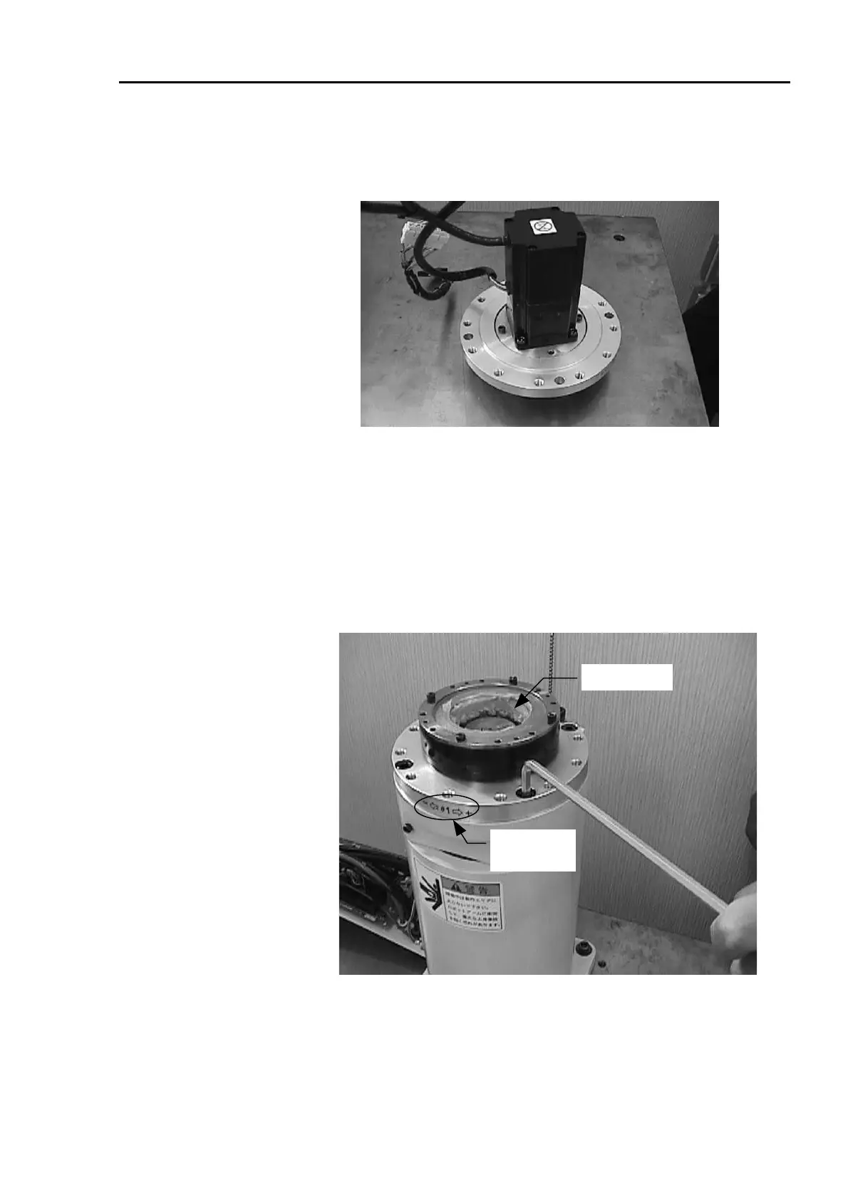
Never touch (to loosen or tighten) the four bolts on the top surface shown in the
picture below. If the bolts are moved, the fleck spline and cross roller bearing unit
must be readjusted at the suppliers since they are centered when attached
together.
Joint label on
the front side
SK-1A grease
(9) As illustrated above, grease inside the reduction gear unit. (ES: 40g; EL: 80g)
NOTE
 Loading...


