7. Replacing the Brake Part 2: Maintenance
154
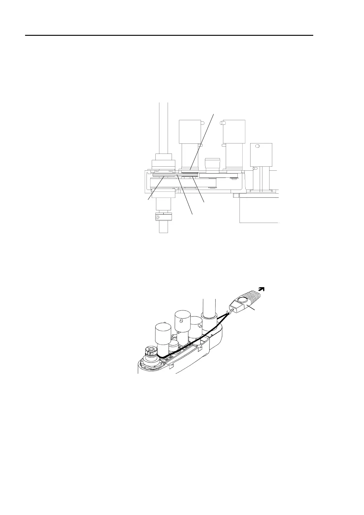
(8) Place the Joint #3 motor unit in the arm. The motor cables should be facing Joint #2.
(9) Fit the Z belt around the Z1 and Z2 pulleys. Ensure that the gear grooves of the belt
and pulleys engage properly. Be careful not to slip the Z belt from the pulleys when
holding proper interval between the pulleys. Fasten the Joint #3 motor plate for the
time being using four bolts (M4×10).
Z1 pulley
Joint #3 Z belt
Z2 pulley
Motor plate
(10) Pass a suitable cord or string around the Joint #3 motor near its mounting plate.
Loosen the bolts for the Joint #3 motor plate fastened in the step (9) and pull the cord
using a force gauge or similar tool. Fasten the Joint #3 motor plate securely where
the Z belt is pulled at 29.4N (3kgf). Adjust in the range of 20N - 39N (2kgf - 4kgf).
Force gauge
(11) Connect the connectors, X131, X31 and X32. Fasten the cables with wire ties in their
original positions. Do not allow unnecessary strain on the cables.
(12) Install the arm top cover and arm bottom cover. (Refer to chapter 2. Opening the
Covers.)
* If the manipulator is a Protected model, seal the arm top cover and arm bottom
cover. Refer to the section Sealing the Manipulator in chapter 13. Protected
Model Maintenance.
(13) The mechanical origin position and teach points change when the motor is replaced.
Be sure to calibrate Joint #3. (Refer to chapter 11. Calibration.)
 Loading...


