Part 2: Maintenance 7. Replacing the Brake
153
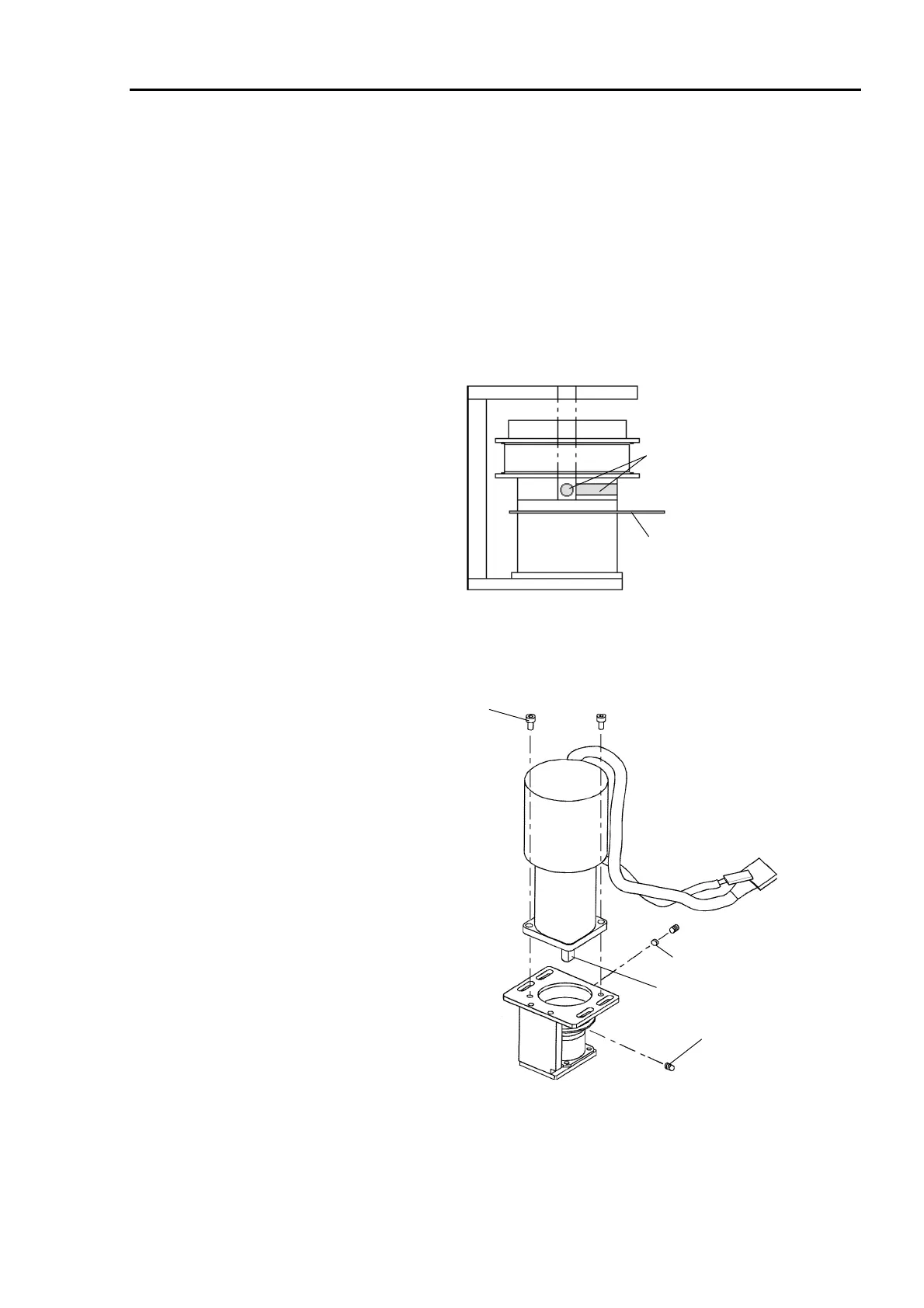
Installation
(1) Fasten the rotor hub of the new brake to the surface of the pulley securely with three
machine screws (M2×3).
(2) Fasten the new brake to the brake plate with four bolts (M3×5).
(3) Fasten the brake cable to the brake plate with a wire tie to prevent interference with the
pulley.
(4) Put a gap gauge (0.15 mm) which was pasted inside the arm bottom cover between the
brake and rotor hub and set the pulley on the brake. At this time, the positions of the
pulley setscrew holes are as shown in the figure below.
Gap gauge
(0.15 mm)
Pulley screw
holes
(5) Place the new motor to the motor plate so that the motor cables turn to the direction of
the figure below and fasten it with two bolts (M4×8). The direction of the motor shaft
flat face should face one of the screw holes of the pulley.
Flat face
M4
×
8
M4
×
8
Flat point setscrew
Bush
(6) Secure the pulley with two flat point setscrews (M4×8). One of the screws should
touch the flat face in the motor shaft perpendicularly. Insert the bush into the other
screw hole and tighten the screw so as not to scratch the motor shaft.
(7) After the pulley is secured, pull out the gap gauge.
 Loading...


