Part 2: Maintenance 13. Protected Model Maintenance
219
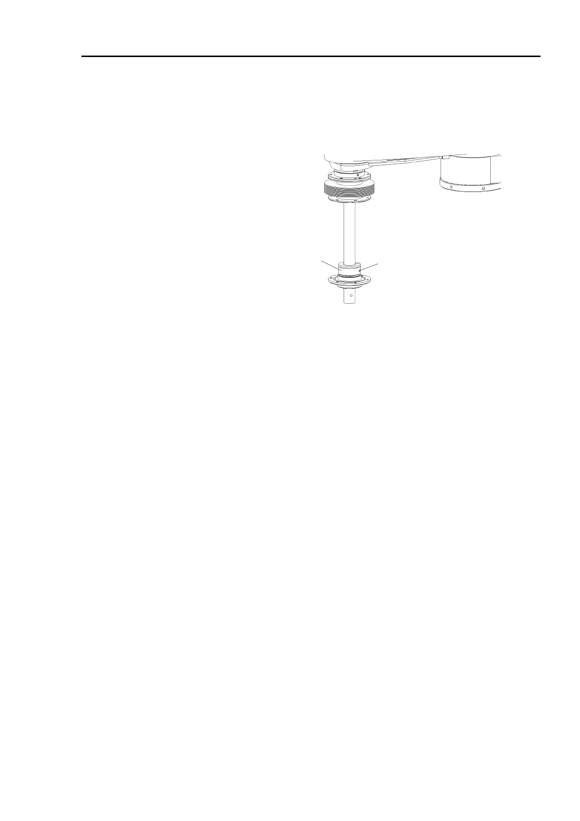
(7) Place the flange on the set-ring. Lower the bearing, spacer and upper-limit
mechanical stop to the bottom.
(8) Secure the upper-limit mechanical stop with a bolt (M4×18).
M4×18 bolt
Upper-limit
mechanical stop
(9) Fit the O-ring into the groove of the flange. Fasten the flange and the mounting ring
on the bottom of the lower bellows with six bolts (M4×6).
(10) Fit the O-ring into the groove of the flange. Fasten the flange and the mounting ring
on the top of the lower bellows with six bolts (M4×6).
(11) To make sure that the bellows can expand and contract smoothly without excessive
force, raise and lower manually Joint #3 while pushing the brake release button and
move Joint #4.
(12) Turn OFF the power to attach the end effector and connect the wiring and piping to the
end effector.
 Loading...


