13. Protected Model Maintenance Part 2: Maintenance
218
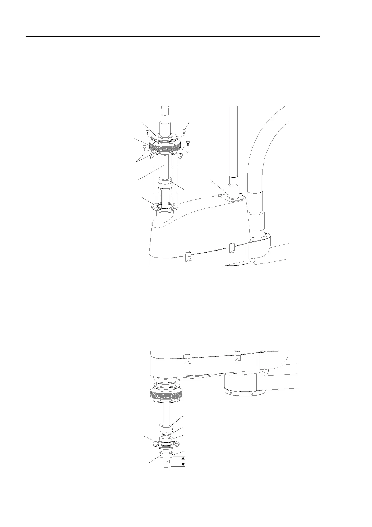
Installation
(1) Attach the mounting rings to both ends of the new bellows.
(2) Pass the shaft through the O-ring, bellows, and O-ring.
(3) Pass the wiring and tubes through the shaft. Mount the extension shaft to the main
shaft with two bolts (M4×15).
Brake release
button
Upper bellows
Extension shaft
(4)
Mounting rings
Flange
(5)
Flange
(3)
(4) Fit the O-ring into the groove of the flange. Fasten the flange and the mounting ring
on the top of the upper bellows with six bolts (M4×6).
(5) Fit the O-ring into the groove of the flange. Fasten the flange and the mounting ring
on the bottom of the upper bellows with six bolts (M4×6).
(6) Pass the shaft through the O-ring, bellows, O-ring, flange, and set-ring. Secure the
set-ring at the 30 mm apart from the end of the shaft with a bolt (M6×18).
M6×18 bolt
Flange
Set-ring
30mm
Spacer
Upper-limit mechanical stop
Bearing
 Loading...


