Part 1: Setup & Operation 8. Motion Range and Robot Coordinates
53
(10) Move Joint #3 slowly using the PULSE command to the position of the lower-limit value of
the pulse range. If the mechanical stop is being hit, or if it is hit and an error occurs, either
narrow the pulse range just enough to eliminate interface, or widen the position of the
mechanical stop. The typical clearance for the mechanical stop at the lower-limit pulse
position is approximately 5 mm.
<Example in (8)>
Execute the following commands from the Monitor Window.
MOTOR ON ' Turn the motor on
SPEED 5 ' Sets on slow speed
PULSE 0,0,-30720,0 ' Moves to lower limit-pulse position of Joint #3.
In the example, all pulses other than that of Joint
#3 are 0. You should substitute these zeroes
with a pulse for a position in which there is no
interference even when you lower Joint #3.
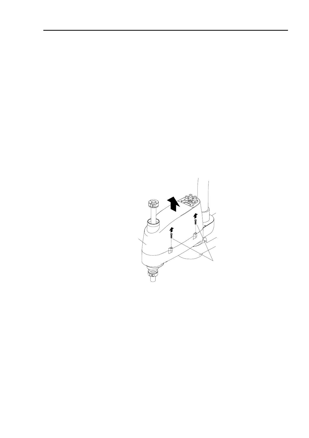
(11) If you need a clear view, remove four mounting bolts (See Figure 32) from the arm cover,
open the cover, and look from the side.
Arm top cover mounting bolts
Arm top cover
Figure 32. Arm top cover
 Loading...


