8. Motion Range and Robot Coordinates Part 1: Setup & Operation
52
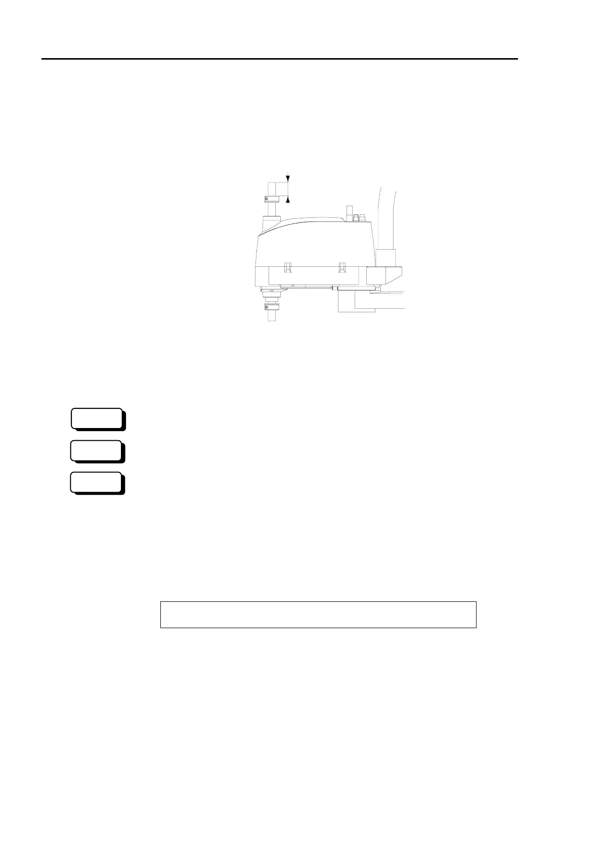
(4) The upper end of the shaft defines the maximum stroke. So, when you want to limit
the stroke, lower the lower-limit mechanical stop by the length you want to limit the
stroke. As an example, let’s say that the lower-limit mechanical stop is set at the
standard 170 mm, making the lower-limit Z coordinate -170 mm. If you want to
make the lower-limit Z coordinate -100 mm, you must lower the lower-limit
mechanical stop 70 mm. Use calipers to measure the distance when you lower the
stop.
Measure a distance
Figure 31. Changing the position of the mechanical stop for Joint #3
(5) Firmly tighten the bolt of the split muff coupling once it is in the appropriate position.
Recommended tightening torque is 490N⋅cm (50kgf⋅cm).
(6) Turn ON the Drive Unit, and start EPSON RC+.
(6) Turn ON the Drive Unit, and start SPEL 95.
(6) Turn ON the controller.
(7) Move the shaft to the lowest position by hand while pushing the brake release button.
Make sure that the shaft is not too high for the operation points.
(8) Calculate the lower-limit pulse of the pulse range using the following formula. (The
lower limit Z coordinate is negative, so always make certain that the result of
calculations is negative.)
Lower limit of pulse = lower limit Z axis value / 20 × 4096 × 1.5
<Example>
The stroke is 170 mm. You lower the mechanical stop 70 mm and change the lower
limit Z coordinate to -100 mm.
(-100) / 20 × 4096 × 1.5 = -30720
(9) Set the pulse range. The upper-limit pulse is 0.
<Example in (8)>
> JRANGE 3,-30720,0
300
RC+
SPEL 95
 Loading...


