Part 1: Setup & Operation 8. Motion Range and Robot Coordinates
51
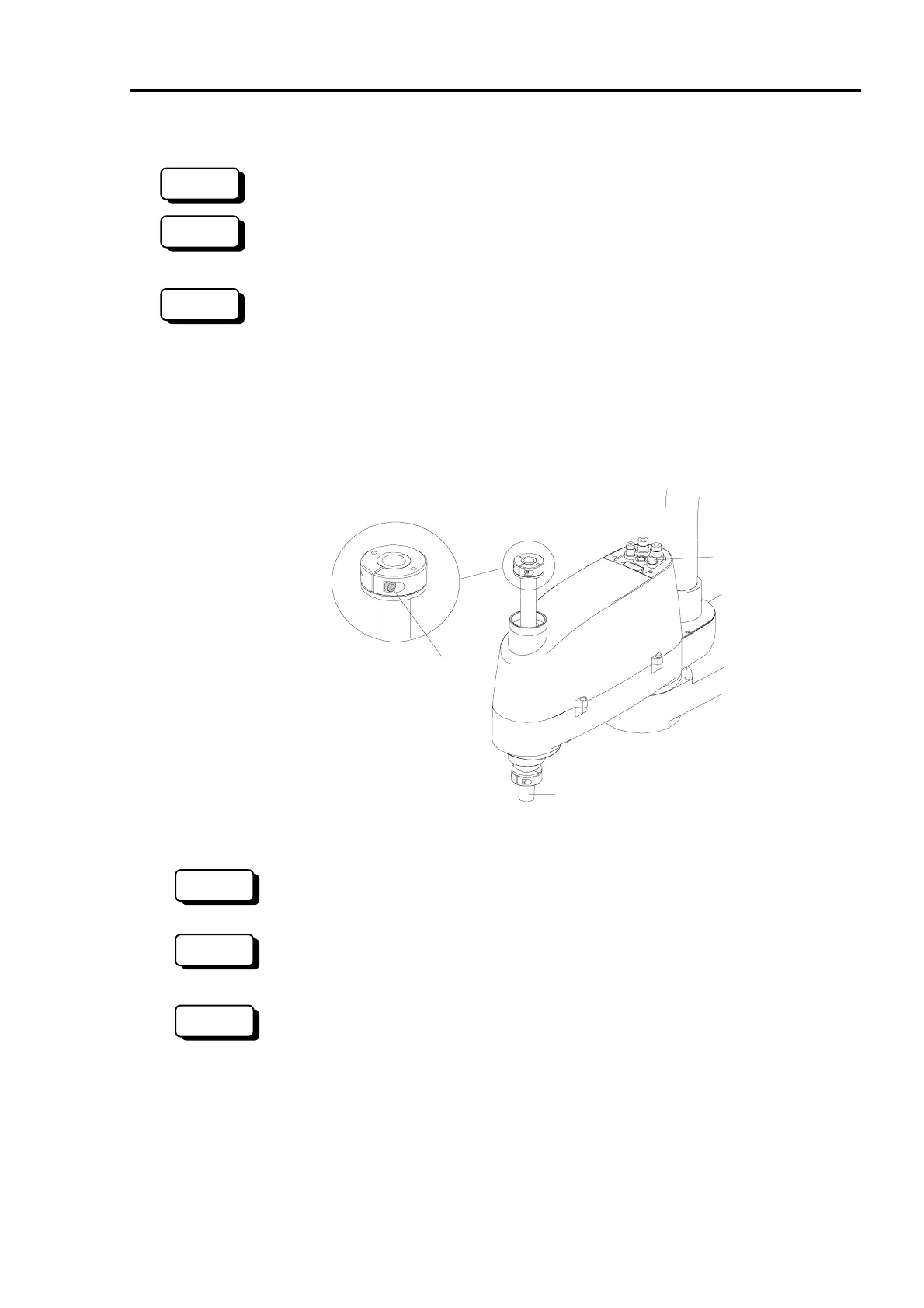
(2) Changing the position of the mechanical stop for Joint #3
* This method applies only to Standard model.
(1) With the Drive Unit ON and the motors OFF (using the MOTOR OFF command),
push the joint #3 brake release button.
(1) With the controller ON and the motors OFF (using the MOTOR OFF command), push
the joint #3 brake release button.
When you push the brake release button, Joint #3 may descend under the weight of the end
effector, so be sure to support the shaft when you push the button.
Joint #3 can be moved up and down while you are holding down the brake release button.
Push the shaft all the way up to the upper limit.
Joint #3 brake
release button
shaft
(3)
Lower limit mechanical
stop for Joint #3
Figure 30. Mechanical stop for Joint #3
(2) Exit EPSON RC+, shut down the SPEL Runtime Drivers, and turn OFF the Drive
Unit.
(2) Exit SPEL 95, and turn OFF the Drive Unit.
(2) Turn OFF the controller.
(3) The lower-limit mechanical stop is a split muff coupling fastened to the top of the shaft.
Loosen the coupling’s M4×15 bolt. (See Figure 30.)
Joint #3 has mechanical stops above and below, but only the lower-limit stop position can
be changed. Do not move the upper-limit mechanical stop, as it also functions as part of
the calibration point detector.
300
NOTE
NOTE
RC+
SPEL 95
SPEL 95
RC+
300
 Loading...


