CX2550 M1 Upgrade and Maintenance Manual 211
12 Appendix
12.1 Mechanical overview
12.1.1 Server node interior
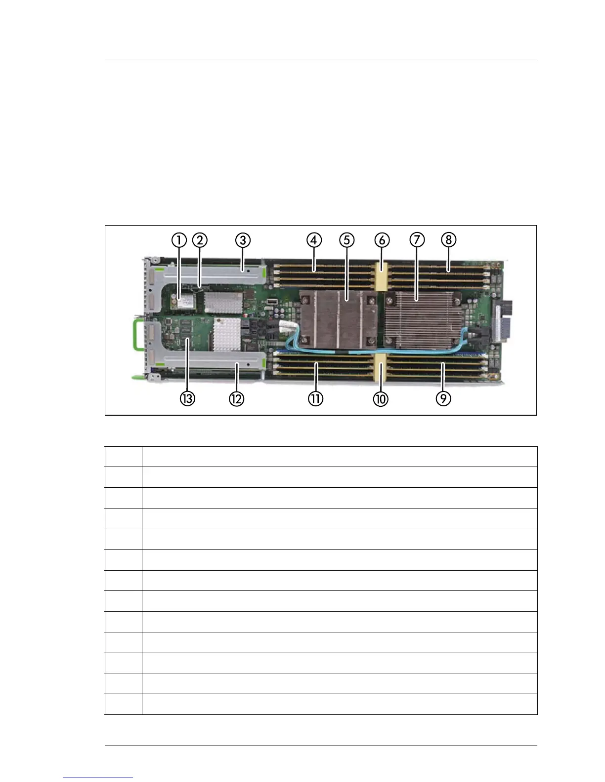
Figure 108: Example: PRIMERGY CX2550 M1 server node interior (with heat sinks)
Pos. Component
1 USB Flash Module (UFM)
2 SATA DOM (not visible, located under the riser module
3 Riser module on the left side
4 Memory slots for CPU1
5 CPU1 with heat sink
6 Memory air duct
7 CPU2 with heat sink
8 Memory slots for CPU2
9 Memory slots for CPU2
10 Memory air duct
11 Memory slots for CPU1
12 Riser module at the right side
 Loading...