12.2.2 Connector panel
12.2.2.1 Controls and indicators
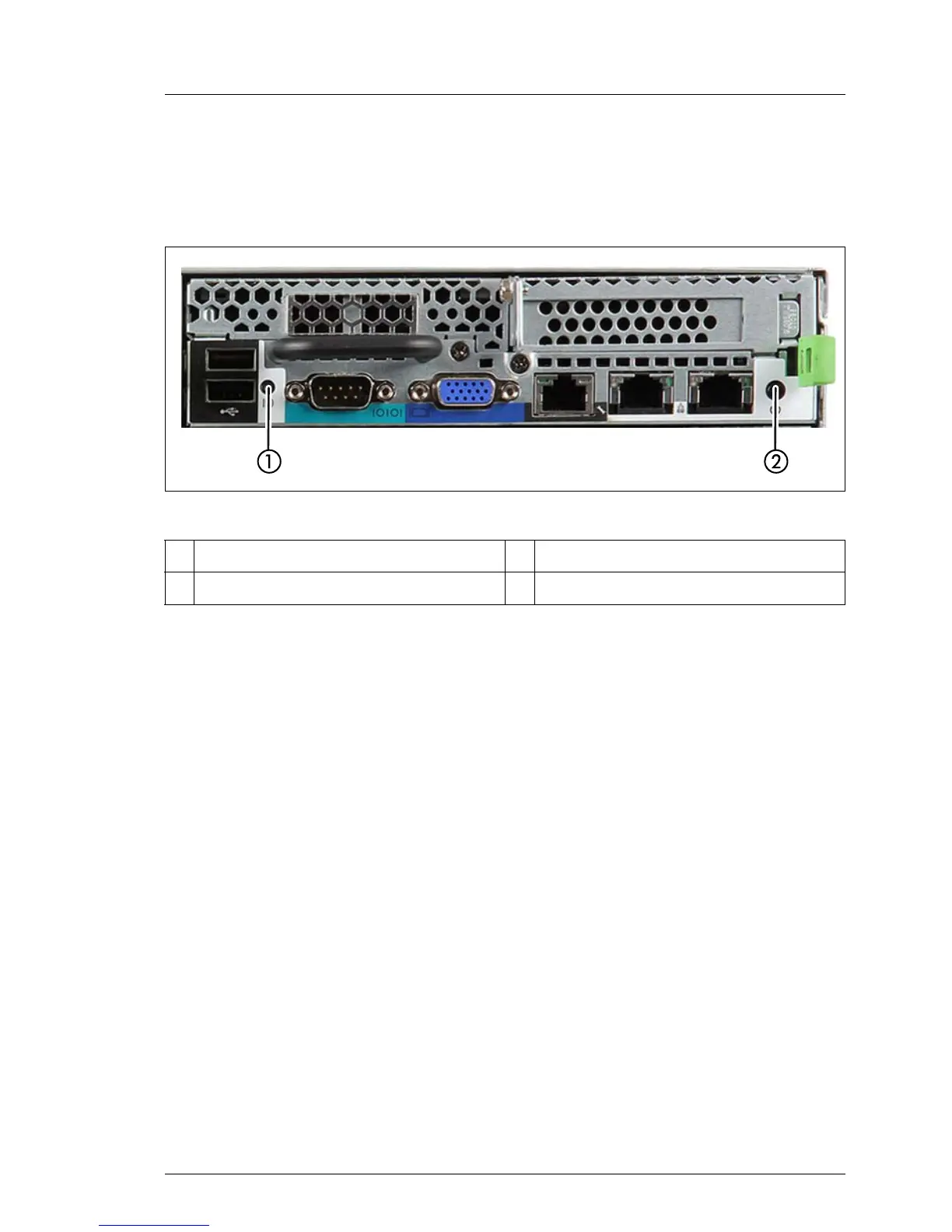
Figure 112: Controls and indicators of the server node
I The server nodes are controlled via related operating panel areas on the
front side of the CX400 M1 server enclosure. See "FUJITSU Server
PRIMERGY CX400 M1 Server Enclosure Operating Manual".
12.2.2.2 Control elements
I The server nodes are controlled via related operating panel areas on the
front side of the CX400 M1 server enclosure. See "FUJITSU Server
PRIMERGY CX400 M1 Server Enclosure Operating Manual".
1
RST button 3 ID indicator
2 Global error indicator 4 CSS indicator
RST Reset button
Pressing the reset button reboots the system.
V CAUTION!
Risk of loss of data!
 Loading...