Section 4
4-76 © Copyright 2009 GBC. All rights reserved. Advanced Punch Service Manual
Procedure
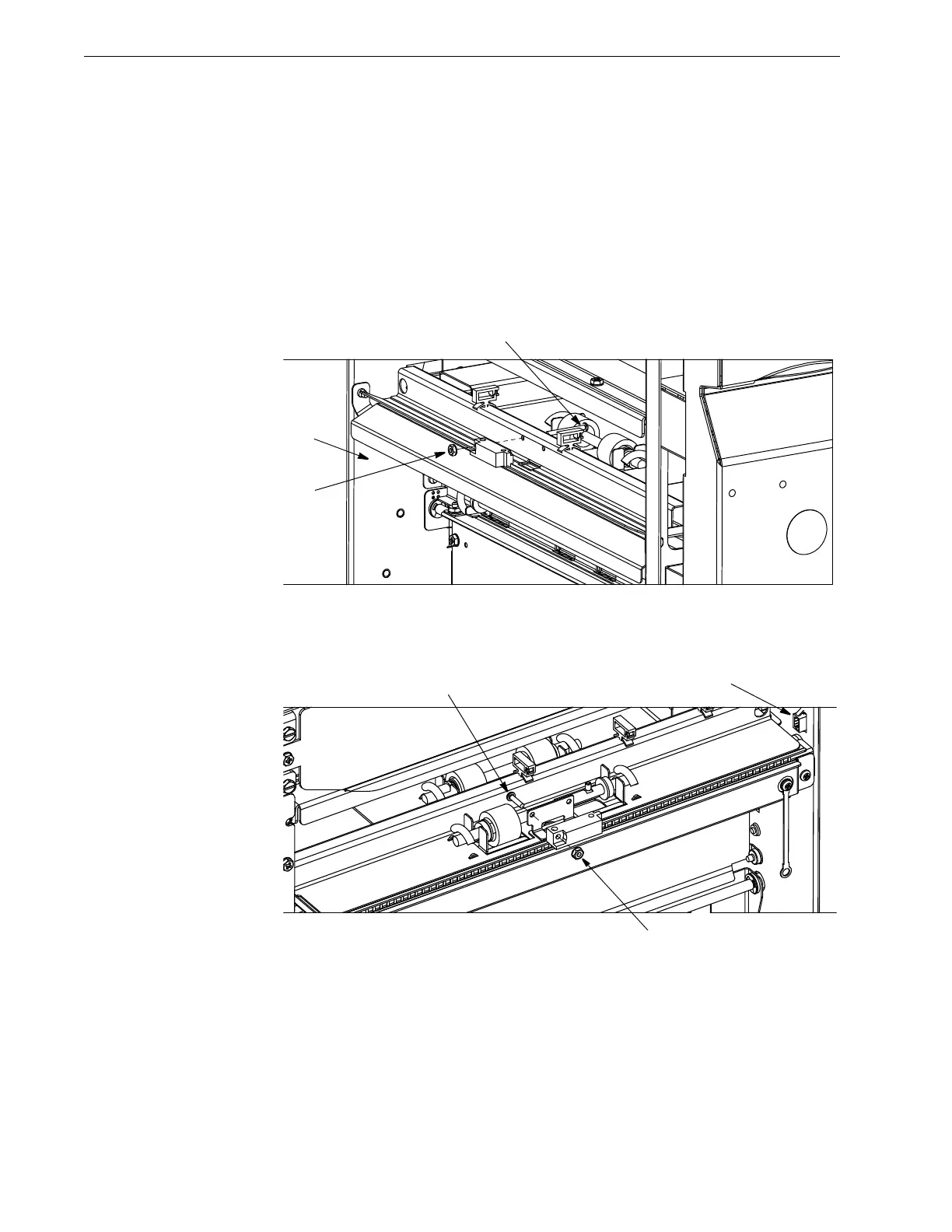
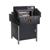
• Replacement of sensor S1 and S7 (See below images)
1. Sensor S1 is located on entry side and S7 is located on exit side.
2. Disconnect the sensor wires from the rear frame [1].
3. Remove the screw [2] and nut [3] that secure the sensor to the sheet metal
part.
4. Reverse the above steps to install the sensor.
Figure 4.91 Sensor S1 Replacement
Figure 4.92 Sensor S7 Replacement
• Replacement of sensor S2 and S6 (See below images)
1. Sensor S2 is located on on entry side and S6 is located on exit side
2. First remove aligner panels entry or exit respectively as per Sec 4.6.2
3. Remove the entrance side drive aligner panel as per 4.6.3.1 or exit side drive