Section 4
4-28 © Copyright 2009 GBC. All rights reserved. Advanced Punch Service Manual
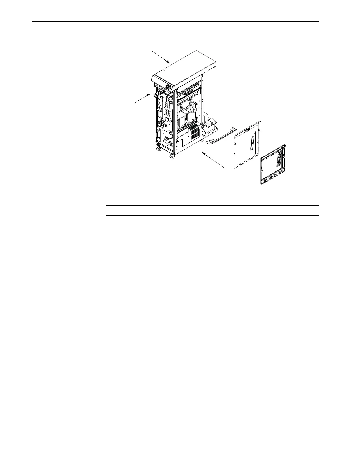
Figure 4.28 Removing the Aligner assembly.
Caution: Walk the Belt off of the Aligner Pulley at the rear.
a. Remove the 2 screws that hold the block to the frame. The Coupler is loose
and the rear panel will come out.
b. Remove the 6 screws that secure the face of this assembly.
c. Remove the 2 screws that secure this assembly from the top.
d. Pull and walk the entire sheet metal assembly of the Paper Guide Aligner
up and outward. You can grab the assembly at the roller cut out with your
fingers.
Caution: Handle the helical coupling carefully. It is very delicate.
Note: In order to access these screws, you must first remove the Die Set storage
shelf and the cable shield attached to the Die storage shelf at the paper entrance
side. Moving the Die Storage shelf aside will enable better access to the 2 screws
with a short Phillips screw driver.
ASSEMBLE BACK
PAPER EXIT
SIDE
FRONT DOOR SIDE
PAPER ENTERANCE