Repair and Adjustment Procedures
Advanced Punch Service Manual © Copyright 2009 GBC. All rights reserved. 4-29
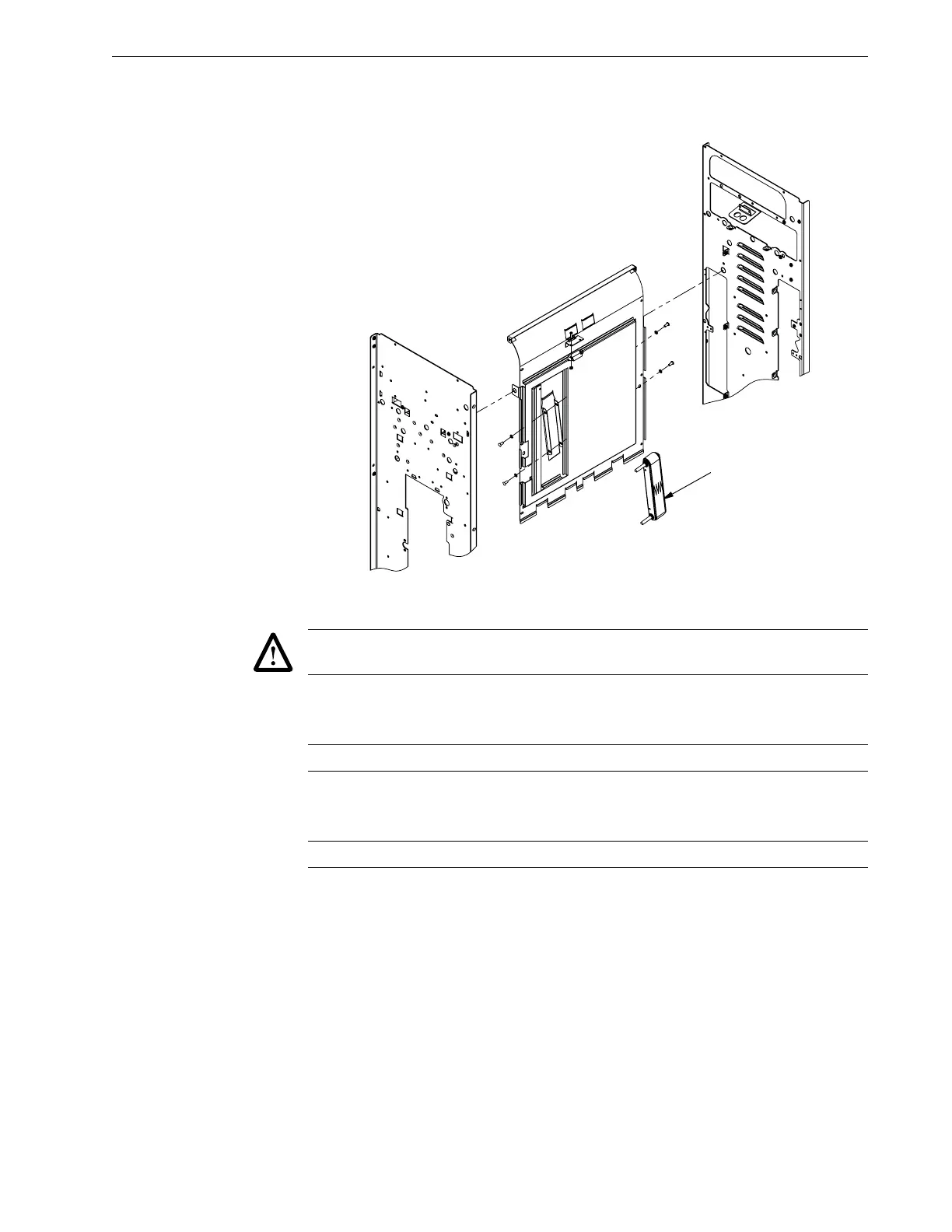
Figure 4.29 Removing the Aligner Drive Belt.
Caution: As you do this, disconnect the sensor harness behind the assembly as soon as
you are able to reach it. Failure to do this can damage the unit.
5. Remove the green drive belt Aligner Roller assembly by removing the 4 screws
(S).
Caution: Leave the Flex Shaft (FS) attached.
6. Remove the green drive belt Aligner Roller assembly by removing the 4
screws.
Caution: Leave the Coupler attached.