5-54 750/760 Feeder Management Relay GE Multilin
5.6 S5 PROTECTION 5 SETPOINTS
5
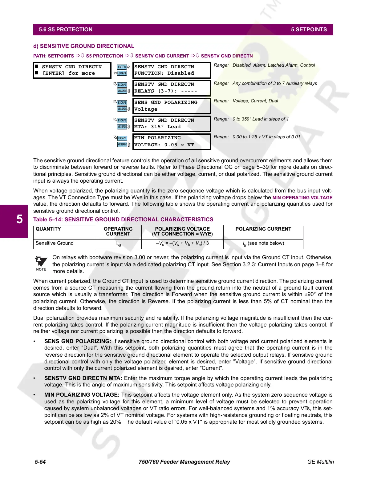
d) SENSITIVE GROUND DIRECTIONAL
PATH: SETPOINTS ÖØ S5 PROTECTION ÖØ SENSTV GND CURRENT ÖØ SENSTV GND DIRECTN
The sensitive ground directional feature controls the operation of all sensitive ground overcurrent elements and allows them
to discriminate between forward or reverse faults. Refer to Phase Directional OC on page 5–39 for more details on direc-
tional principles. Sensitive ground directional can be either voltage, current, or dual polarized. The sensitive ground current
input is always the operating current.
When voltage polarized, the polarizing quantity is the zero sequence voltage which is calculated from the bus input volt-
ages. The VT Connection Type must be Wye in this case. If the polarizing voltage drops below the
MIN OPERATING VOLTAGE
value, the direction defaults to forward. The following table shows the operating current and polarizing quantities used for
sensitive ground directional control.
On relays with bootware revision 3.00 or newer, the polarizing current is input via the Ground CT input. Otherwise,
the polarizing current is input via a dedicated polarizing CT input. See Section 3.2.3: Current Inputs on page 3–8 for
more details.
When current polarized, the Ground CT Input is used to determine sensitive ground current direction. The polarizing current
comes from a source CT measuring the current flowing from the ground return into the neutral of a ground fault current
source which is usually a transformer. The direction is Forward when the sensitive ground current is within ±90° of the
polarizing current. Otherwise, the direction is Reverse. If the polarizing current is less than 5% of CT nominal then the
direction defaults to forward.
Dual polarization provides maximum security and reliability. If the polarizing voltage magnitude is insufficient then the cur-
rent polarizing takes control. If the polarizing current magnitude is insufficient then the voltage polarizing takes control. If
neither voltage nor current polarizing is possible then the direction defaults to forward.
• SENS GND POLARIZING: If sensitive ground directional control with both voltage and current polarized elements is
desired, enter "Dual". With this setpoint, both polarizing quantities must agree that the operating current is in the
reverse direction for the sensitive ground directional element to operate the selected output relays. If sensitive ground
directional control with only the voltage polarized element is desired, enter "Voltage". If sensitive ground directional
control with only the current polarized element is desired, enter "Current".
• SENSTV GND DIRECTN MTA: Enter the maximum torque angle by which the operating current leads the polarizing
voltage. This is the angle of maximum sensitivity. This setpoint affects voltage polarizing only.
• MIN POLARIZING VOLTAGE: This setpoint affects the voltage element only. As the system zero sequence voltage is
used as the polarizing voltage for this element, a minimum level of voltage must be selected to prevent operation
caused by system unbalanced voltages or VT ratio errors. For well-balanced systems and 1% accuracy VTs, this set-
point can be as low as 2% of VT nominal voltage. For systems with high-resistance grounding or floating neutrals, this
setpoint can be as high as 20%. The default value of "0.05 x VT" is appropriate for most solidly grounded systems.
SENSTV GND DIRECTN
[ENTER] for more
SENSTV GND DIRECTN
FUNCTION: Disabled
Range: Disabled, Alarm, Latched Alarm, Control
SENSTV GND DIRECTN
RELAYS (3-7): -----
Range: Any combination of 3 to 7 Auxiliary relays
SENS GND POLARIZING
Voltage
Range: Voltage, Current, Dual
SENSTV GND DIRECTN
MTA: 315° Lead
Range: 0 to 359° Lead in steps of 1
MIN POLARIZING
VOLTAGE: 0.05 x VT
Range: 0.00 to 1.25 x VT in steps of 0.01
Table 5–14: SENSITIVE GROUND DIRECTIONAL CHARACTERISTICS
QUANTITY OPERATING
CURRENT
POLARIZING VOLTAGE
(VT CONNECTION = WYE)
POLARIZING CURRENT
Sensitive Ground I
sg
–V
o
= –(V
a
+ V
b
+ V
c
) / 3 I
g
(see note below)
ENTER
ESCAPE
ð
ð
MESSAGE
ESCAPE
MESSAGE
ESCAPE
MESSAGE
ESCAPE
MESSAGE
ESCAPE
NOTE
Courtesy of NationalSwitchgear.com
 Loading...


