5-56 750/760 Feeder Management Relay GE Multilin
5.6 S5 PROTECTION 5 SETPOINTS
5
To determine the appropriate value for the Stabilizing Resistor, use the following equation:
(EQ 5.5)
where: R
S
= resistance value of the stabilizing resistor, V
S
= voltage at which the 750/760 will operate
I
S
= current flowing through the stabilizing resistor and the 750/760,
I
F
= maximum secondary fault current magnitude
R
CT
= internal resistance of the current transformer, and R
L
= resistance of attached wire leads
A non-linear resistor is recommended if the peak fault voltage may be above the relays maximum of 2000 V. The following
calculation is done to determine if a non-linear resistor is required. When required, this should be provided by the end-user.
It is assumed that the ratio of the CT kneepoint (V
K
) V
S
is to 2 for stability. Thus,
(EQ 5.6)
Next, the voltage that would result from a fault must be determined, neglecting saturation,
(EQ 5.7)
The peak value of this fault voltage would be:
(EQ 5.8)
If V
P
is greater than 2000 V, then a non-linear resistor must be used.
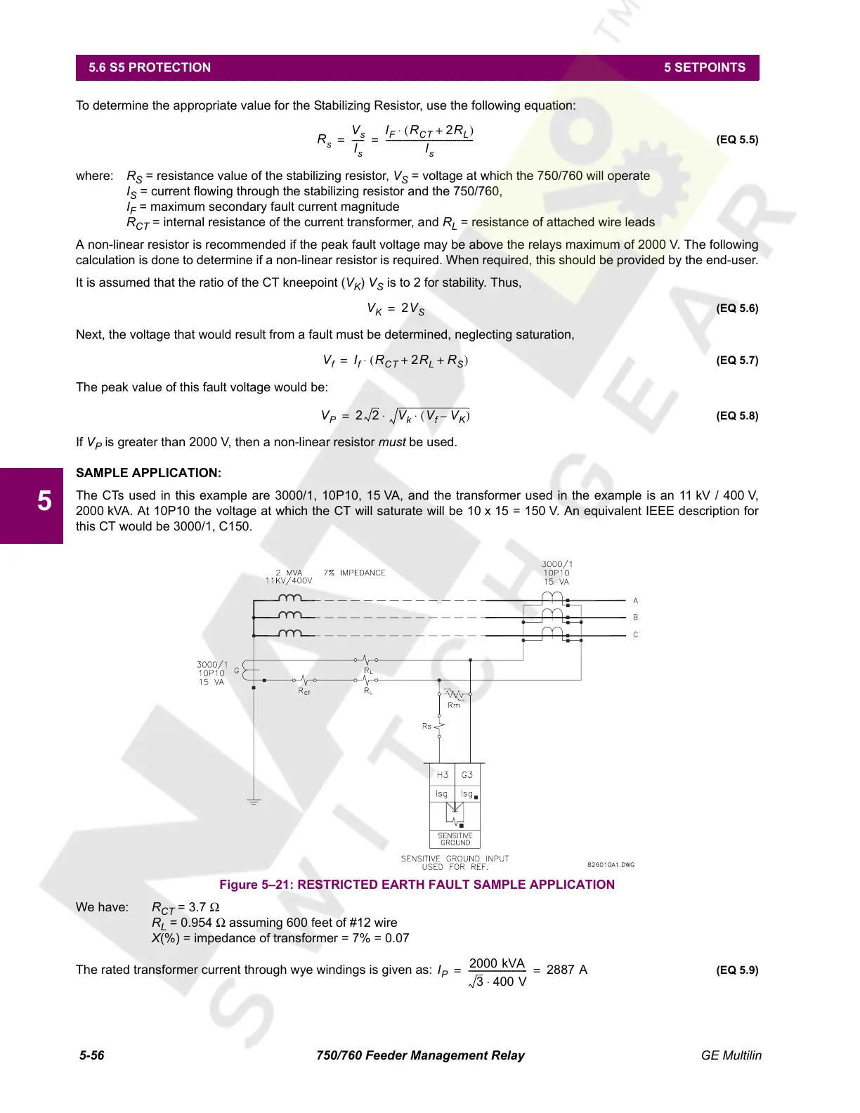
SAMPLE APPLICATION:
The CTs used in this example are 3000/1, 10P10, 15 VA, and the transformer used in the example is an 11 kV / 400 V,
2000 kVA. At 10P10 the voltage at which the CT will saturate will be 10 x 15 = 150 V. An equivalent IEEE description for
this CT would be 3000/1, C150.
Figure 5–21: RESTRICTED EARTH FAULT SAMPLE APPLICATION
We have: R
CT
= 3.7 Ω
R
L
= 0.954 Ω assuming 600 feet of #12 wire
X(%) = impedance of transformer = 7% = 0.07
The rated transformer current through wye windings is given as:
(EQ 5.9)
R
s
V
s
I
s
------
I
F
R
CT
2R
L
+()⋅
I
s
----------------------------------------- -==
V
K
2V
S
=
V
f
I
f
R
CT
2R
L
R
S
++()⋅=
V
P
22 V
k
V
f
V
K
–()⋅⋅=
I
P
2000 kVA
3 400 V⋅
--------------------------- - 2887 A==
Courtesy of NationalSwitchgear.com
 Loading...


