GE Multilin 750/760 Feeder Management Relay 5-57
5 SETPOINTS 5.6 S5 PROTECTION
5
and the maximum fault current is: (EQ 5.10)
Therefore, the secondary full load current is: (EQ 5.11)
and the maximum secondary fault current is: (EQ 5.12)
A V
K
/ V
S
ratio of 2 is assumed to ensure operation. As such,
V
S
= I
f
(R
CT
+ 2R
L
) = 77.05 V and
V
K
= 2V
S
= 154.1 V
To calculate the size of the stabilizing resistor, assume I
PICKUP
to be 30% rated transformer current, that is:
(EQ 5.13)
This means also (assuming 1% for CT magnetizing current):
(EQ 5.14)
and therefore:
(EQ 5.15)
To determine whether a non-linear resistor is required, we have:
(EQ 5.16)
A non-linear resistor is recommended as the peak fault voltage is above relay voltage maximum of 2000 V.
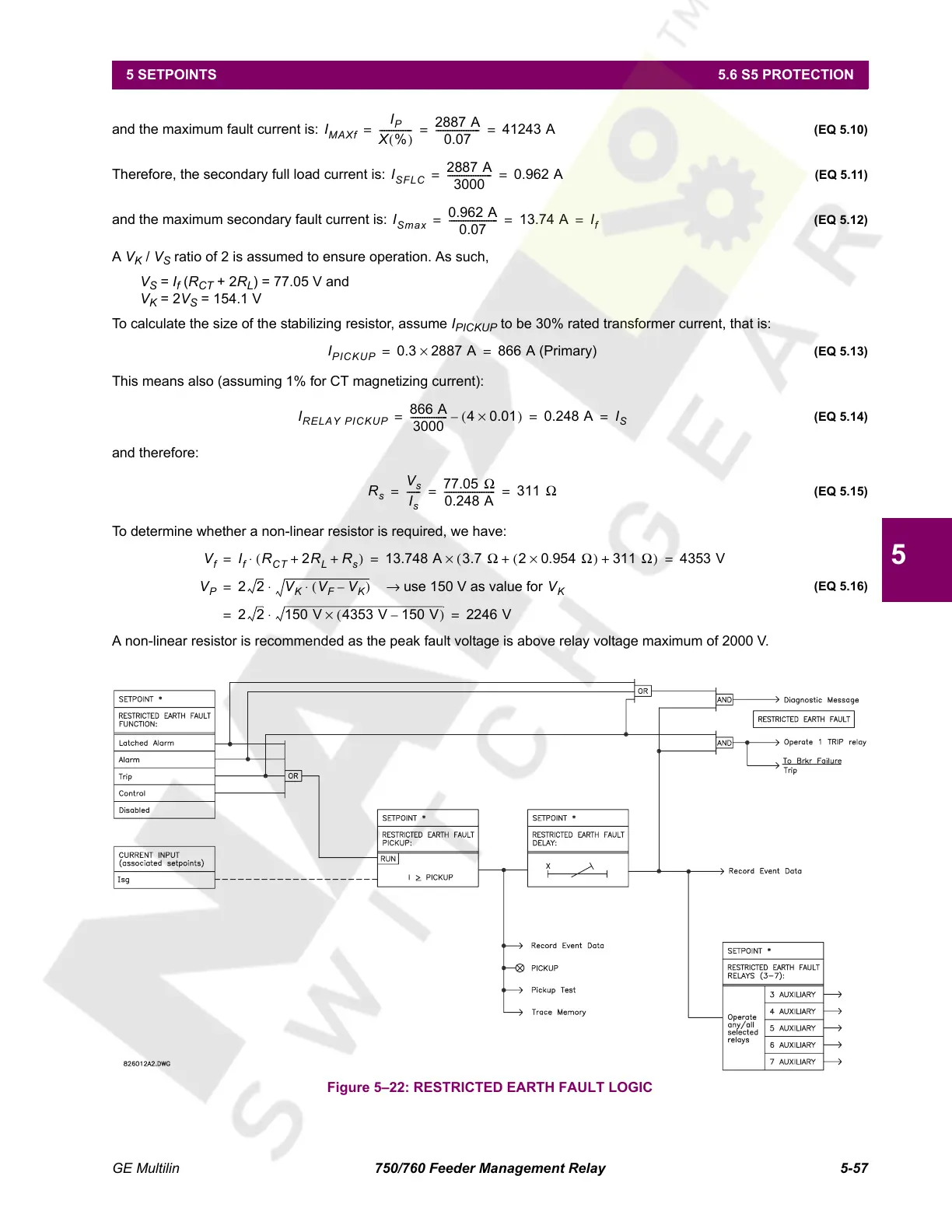
Figure 5–22: RESTRICTED EARTH FAULT LOGIC
I
MAXf
I
P
X %()
--------------
2887 A
0.07
------------------- 41243 A== =
I
SFLC
2887 A
3000
------------------- 0.962 A==
I
Smax
0.962 A
0.07
-------------------- - 13.74 A I
f
===
I
PICKUP
0.3 2887 A× 866 A (Primary)==
I
RELAY PICKUP
866 A
3000
--------------- - 40.01×()– 0.248 A I
S
===
R
s
V
s
I
s
------
77.05 Ω
0.248 A
--------------------- - 311 Ω== =
V
f
I
f
R
CT
2R
L
R
s
++()⋅ 13.748 A 3.7 Ω 20.954 Ω×()311 Ω++()× 4353 V== =
V
P
22 V
K
V
F
V
K
–()⋅ use 150 V as value for → V
K
⋅=
2 2 150 V 4353 V 150 V–()×⋅ 2246 V==
Courtesy of NationalSwitchgear.com
 Loading...


