5-64 750/760 Feeder Management Relay GE Multilin
5.6 S5 PROTECTION 5 SETPOINTS
5
b) BUS UNDERVOLTAGE
PATH: SETPOINTS ÖØ S5 PROTECTION ÖØ VOLTAGE Ö BUS UNDERVOLTAGE 1(2)
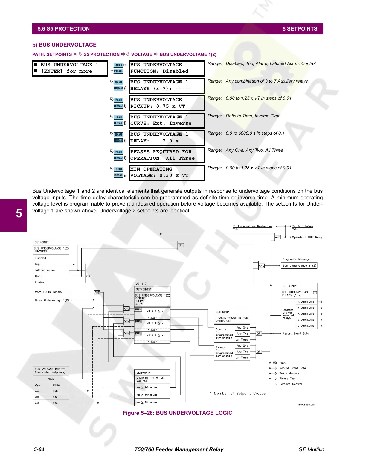
Bus Undervoltage 1 and 2 are identical elements that generate outputs in response to undervoltage conditions on the bus
voltage inputs. The time delay characteristic can be programmed as definite time or inverse time. A minimum operating
voltage level is programmable to prevent undesired operation before voltage becomes available. The setpoints for Under-
voltage 1 are shown above; Undervoltage 2 setpoints are identical.
Figure 5–28: BUS UNDERVOLTAGE LOGIC
BUS UNDERVOLTAGE 1
[ENTER] for more
BUS UNDERVOLTAGE 1
FUNCTION: Disabled
Range: Disabled, Trip, Alarm, Latched Alarm, Control
BUS UNDERVOLTAGE 1
RELAYS (3-7): -----
Range: Any combination of 3 to 7 Auxiliary relays
BUS UNDERVOLTAGE 1
PICKUP: 0.75 x VT
Range: 0.00 to 1.25 x VT in steps of 0.01
BUS UNDERVOLTAGE 1
CURVE: Ext. Inverse
Range: Definite Time, Inverse Time.
BUS UNDERVOLTAGE 1
DELAY: 2.0 s
Range: 0.0 to 6000.0 s in steps of 0.1
PHASES REQUIRED FOR
OPERATION: All Three
Range: Any One, Any Two, All Three
MIN OPERATING
VOLTAGE: 0.30 x VT
Range: 0.00 to 1.25 x VT in steps of 0.01
ENTER
ESCAPE
ð
ð
MESSAGE
ESCAPE
MESSAGE
ESCAPE
MESSAGE
ESCAPE
MESSAGE
ESCAPE
MESSAGE
ESCAPE
MESSAGE
ESCAPE
Courtesy of NationalSwitchgear.com
 Loading...


