GE Multilin 750/760 Feeder Management Relay 5-65
5 SETPOINTS 5.6 S5 PROTECTION
5
c) LINE UNDERVOLTAGE
PATH: SETPOINTS ÖØ S5 PROTECTION ÖØ VOLTAGE ÖØ LINE UNDERVOLTAGE 3(4)
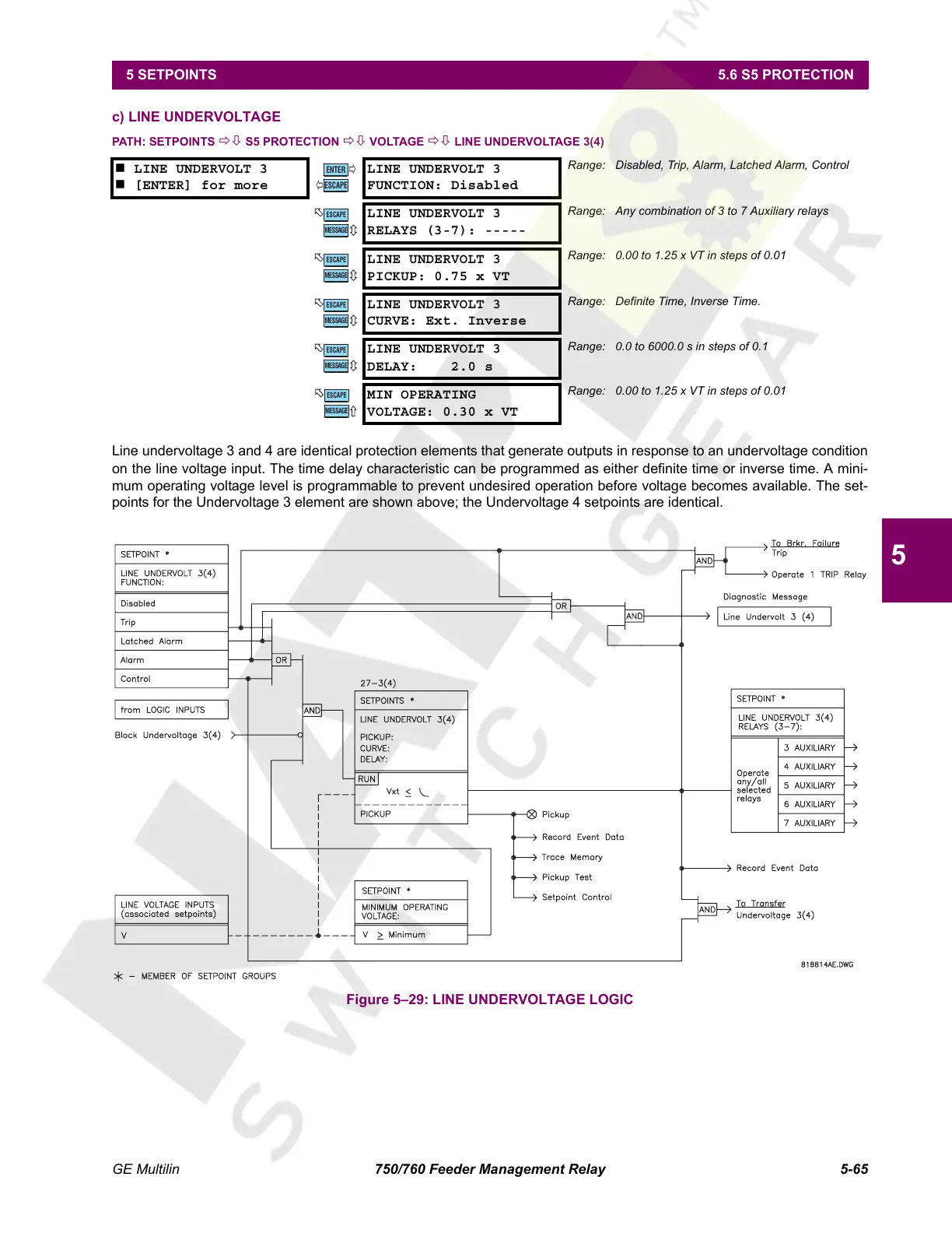
Line undervoltage 3 and 4 are identical protection elements that generate outputs in response to an undervoltage condition
on the line voltage input. The time delay characteristic can be programmed as either definite time or inverse time. A mini-
mum operating voltage level is programmable to prevent undesired operation before voltage becomes available. The set-
points for the Undervoltage 3 element are shown above; the Undervoltage 4 setpoints are identical.
Figure 5–29: LINE UNDERVOLTAGE LOGIC
LINE UNDERVOLT 3
[ENTER] for more
LINE UNDERVOLT 3
FUNCTION: Disabled
Range: Disabled, Trip, Alarm, Latched Alarm, Control
LINE UNDERVOLT 3
RELAYS (3-7): -----
Range: Any combination of 3 to 7 Auxiliary relays
LINE UNDERVOLT 3
PICKUP: 0.75 x VT
Range: 0.00 to 1.25 x VT in steps of 0.01
LINE UNDERVOLT 3
CURVE: Ext. Inverse
Range: Definite Time, Inverse Time.
LINE UNDERVOLT 3
DELAY: 2.0 s
Range: 0.0 to 6000.0 s in steps of 0.1
MIN OPERATING
VOLTAGE: 0.30 x VT
Range: 0.00 to 1.25 x VT in steps of 0.01
ENTER
ESCAPE
ð
ð
MESSAGE
ESCAPE
MESSAGE
ESCAPE
MESSAGE
ESCAPE
MESSAGE
ESCAPE
MESSAGE
ESCAPE
Courtesy of NationalSwitchgear.com
 Loading...


