GE Multilin 750/760 Feeder Management Relay 7-5
7 COMMUNICATIONS 7.3 MODBUS OPERATIONS
7
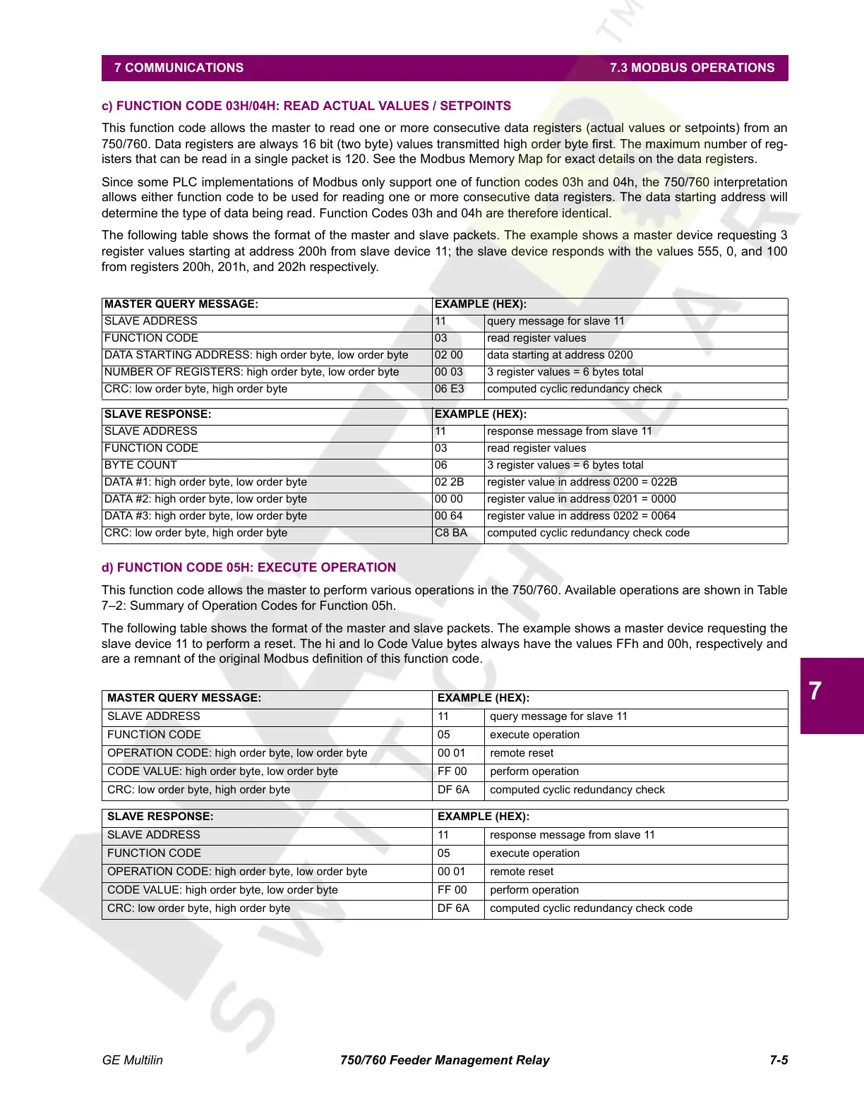
c) FUNCTION CODE 03H/04H: READ ACTUAL VALUES / SETPOINTS
This function code allows the master to read one or more consecutive data registers (actual values or setpoints) from an
750/760. Data registers are always 16 bit (two byte) values transmitted high order byte first. The maximum number of reg-
isters that can be read in a single packet is 120. See the Modbus Memory Map for exact details on the data registers.
Since some PLC implementations of Modbus only support one of function codes 03h and 04h, the 750/760 interpretation
allows either function code to be used for reading one or more consecutive data registers. The data starting address will
determine the type of data being read. Function Codes 03h and 04h are therefore identical.
The following table shows the format of the master and slave packets. The example shows a master device requesting 3
register values starting at address 200h from slave device 11; the slave device responds with the values 555, 0, and 100
from registers 200h, 201h, and 202h respectively.
d) FUNCTION CODE 05H: EXECUTE OPERATION
This function code allows the master to perform various operations in the 750/760. Available operations are shown in Table
7–2: Summary of Operation Codes for Function 05h.
The following table shows the format of the master and slave packets. The example shows a master device requesting the
slave device 11 to perform a reset. The hi and lo Code Value bytes always have the values FFh and 00h, respectively and
are a remnant of the original Modbus definition of this function code.
MASTER QUERY MESSAGE: EXAMPLE (HEX):
SLAVE ADDRESS 11 query message for slave 11
FUNCTION CODE 03 read register values
DATA STARTING ADDRESS: high order byte, low order byte 02 00 data starting at address 0200
NUMBER OF REGISTERS: high order byte, low order byte 00 03 3 register values = 6 bytes total
CRC: low order byte, high order byte 06 E3 computed cyclic redundancy check
SLAVE RESPONSE: EXAMPLE (HEX):
SLAVE ADDRESS 11 response message from slave 11
FUNCTION CODE 03 read register values
BYTE COUNT 06 3 register values = 6 bytes total
DATA #1: high order byte, low order byte 02 2B register value in address 0200 = 022B
DATA #2: high order byte, low order byte 00 00 register value in address 0201 = 0000
DATA #3: high order byte, low order byte 00 64 register value in address 0202 = 0064
CRC: low order byte, high order byte C8 BA computed cyclic redundancy check code
MASTER QUERY MESSAGE: EXAMPLE (HEX):
SLAVE ADDRESS 11 query message for slave 11
FUNCTION CODE 05 execute operation
OPERATION CODE: high order byte, low order byte 00 01 remote reset
CODE VALUE: high order byte, low order byte FF 00 perform operation
CRC: low order byte, high order byte DF 6A computed cyclic redundancy check
SLAVE RESPONSE: EXAMPLE (HEX):
SLAVE ADDRESS 11 response message from slave 11
FUNCTION CODE 05 execute operation
OPERATION CODE: high order byte, low order byte 00 01 remote reset
CODE VALUE: high order byte, low order byte FF 00 perform operation
CRC: low order byte, high order byte DF 6A computed cyclic redundancy check code
Courtesy of NationalSwitchgear.com
 Loading...


