7-14 750/760 Feeder Management Relay GE Multilin
7.4 MODBUS MEMORY MAP 7 COMMUNICATIONS
7
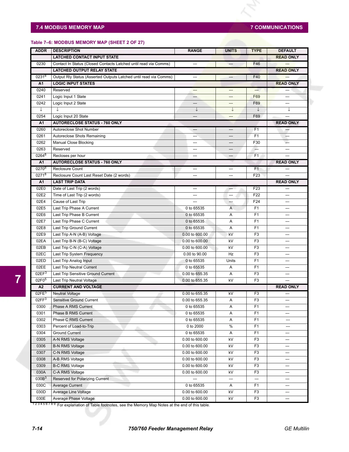
LATCHED CONTACT INPUT STATE READ ONLY
0230 Contact In Status (Closed Contacts Latched until read via Comms) --- --- F46 ---
LATCHED OUTPUT RELAY STATE READ ONLY
0231
8
Output Rly Status (Asserted Outputs Latched until read via Comms) --- --- F40 ---
A1 LOGIC INPUT STATES READ ONLY
0240 Reserved --- --- --- ---
0241 Logic Input 1 State --- --- F69 ---
0242 Logic Input 2 State --- --- F69 ---
↓↓ ↓↓↓↓
0254 Logic Input 20 State --- --- F69 ---
A1 AUTORECLOSE STATUS - 760 ONLY READ ONLY
0260 Autoreclose Shot Number --- --- F1 ---
0261 Autoreclose Shots Remaining --- --- F1 ---
0262 Manual Close Blocking --- --- F30 ---
0263 Reserved --- --- --- ---
0264
8
Recloses per hour --- --- F1 ---
A1 AUTORECLOSE STATUS - 760 ONLY READ ONLY
0270
8
Reclosure Count --- --- F1 ---
0271
8
Reclosure Count Last Reset Date (2 words) --- --- F23 ---
A1 LAST TRIP DATA READ ONLY
02E0 Date of Last Trip (2 words) --- --- F23 ---
02E2 Time of Last Trip (2 words) --- --- F22 ---
02E4 Cause of Last Trip --- --- F24 ---
02E5 Last Trip Phase A Current 0 to 65535 A F1 ---
02E6 Last Trip Phase B Current 0 to 65535 A F1 ---
02E7 Last Trip Phase C Current 0 to 65535 A F1 ---
02E8 Last Trip Ground Current 0 to 65535 A F1 ---
02E9 Last Trip A-N (A-B) Voltage 0.00 to 600.00 kV F3 ---
02EA Last Trip B-N (B-C) Voltage 0.00 to 600.00 kV F3 ---
02EB Last Trip C-N (C-A) Voltage 0.00 to 600.00 kV F3 ---
02EC Last Trip System Frequency 0.00 to 90.00 Hz F3 ---
02ED Last Trip Analog Input 0 to 65535 Units F1 ---
02EE Last Trip Neutral Current 0 to 65535 A F1 ---
02EF
3
Last Trip Sensitive Ground Current 0.00 to 655.35 A F3 ---
02F0
5
Last Trip Neutral Voltage 0.00 to 655.35 kV F3 ---
A2 CURRENT AND VOLTAGE READ ONLY
02FE
5
Neutral Voltage 0.00 to 655.35 kV F3 ---
02FF
3
Sensitive Ground Current 0.00 to 655.35 A F3 ---
0300 Phase A RMS Current 0 to 65535 A F1 ---
0301 Phase B RMS Current 0 to 65535 A F1 ---
0302 Phase C RMS Current 0 to 65535 A F1 ---
0303 Percent of Load-to-Trip 0 to 2000 % F1 ---
0304 Ground Current 0 to 65535 A F1 ---
0305 A-N RMS Voltage 0.00 to 600.00 kV F3 ---
0306 B-N RMS Voltage 0.00 to 600.00 kV F3 ---
0307 C-N RMS Voltage 0.00 to 600.00 kV F3 ---
0308 A-B RMS Voltage 0.00 to 600.00 kV F3 ---
0309 B-C RMS Voltage 0.00 to 600.00 kV F3 ---
030A C-A RMS Voltage 0.00 to 600.00 kV F3 ---
030B
3
Reserved for Polarizing Current --- --- --- ---
030C Average Current 0 to 65535 A F1 ---
030D Average Line Voltage 0.00 to 600.00 kV F3 ---
030E Average Phase Voltage 0.00 to 600.00 kV F3 ---
Table 7–6: MODBUS MEMORY MAP (SHEET 2 OF 27)
ADDR DESCRIPTION RANGE UNITS TYPE DEFAULT
1 2 3 4 5 6 7 8 9
For explanation of Table footnotes, see the Memory Map Notes at the end of this table.
Courtesy of NationalSwitchgear.com
 Loading...


